Common Forces
Original textbook reading.
Another force that is usually common in a lot of everyday situations is tensionⓘ. Tension forces, usually written as or tend to occur in systems wherever there is a rope, cable, string, or some type of attachment to an object.
It is a very important force to consider because without it, there would be no way to pull a piano up a 50 story building, or climb up that rope in gym class because there would be no force in the rope to support your weight. It’s so important, that we’re going to introduce a new system involving tension known as pulleys.
In Figure 2.2.1, a box is being pulled by a force to the right side, but the box is attached by a rope to a hook that is mounted on a wall. So, if you were to imagine pulling the box, you would expect some resistance from the rope.
The resistance you would feel that is preventing the box from moving any further is due to the rope holding the box back. This is the tension force. Since there are forces acting on our object, let’s draw our FBD for this system .
Figure 2.2.1 Tension
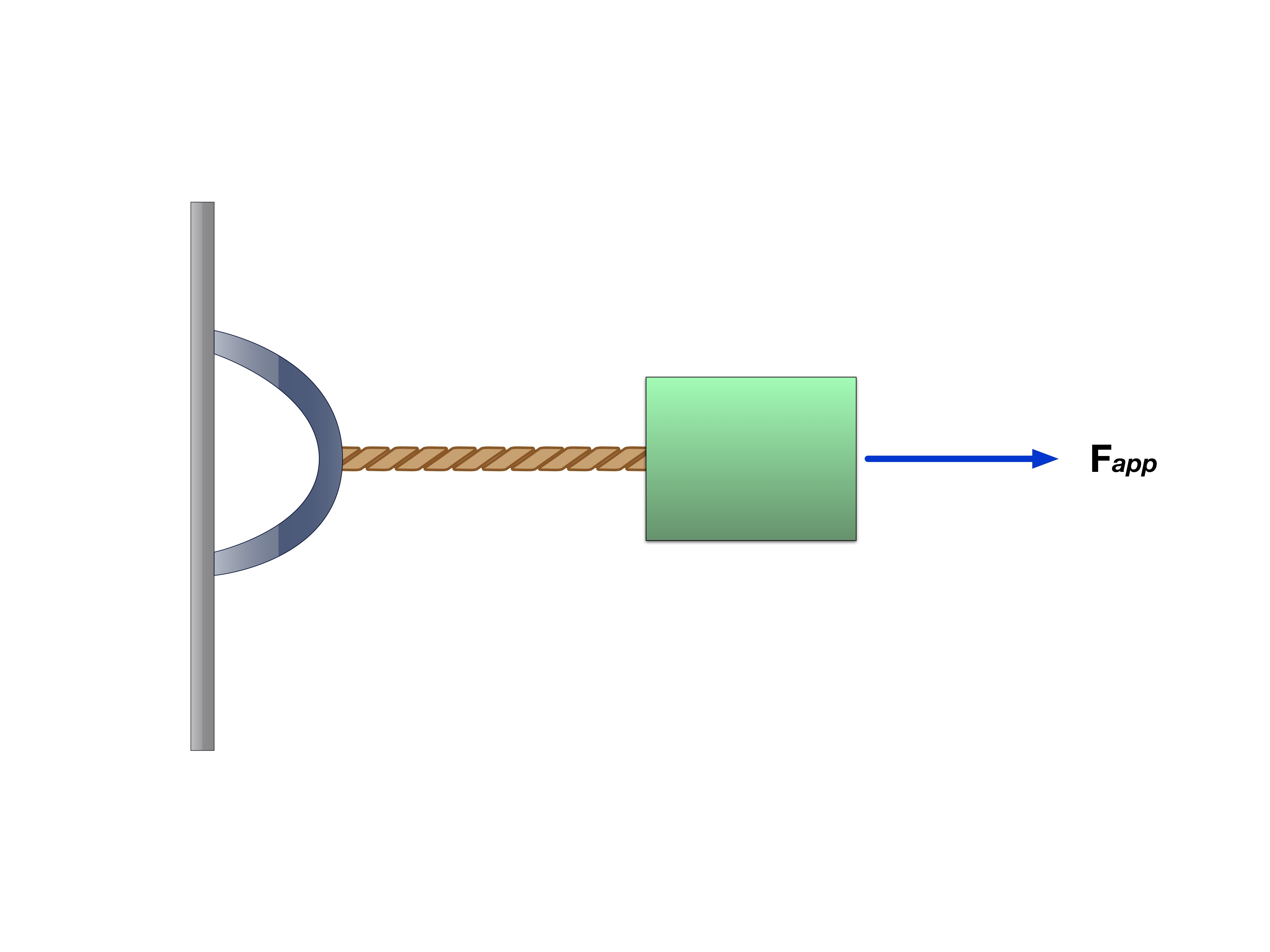
Figure 2.2.2 Free Body Diagram of Figure 2.2.1
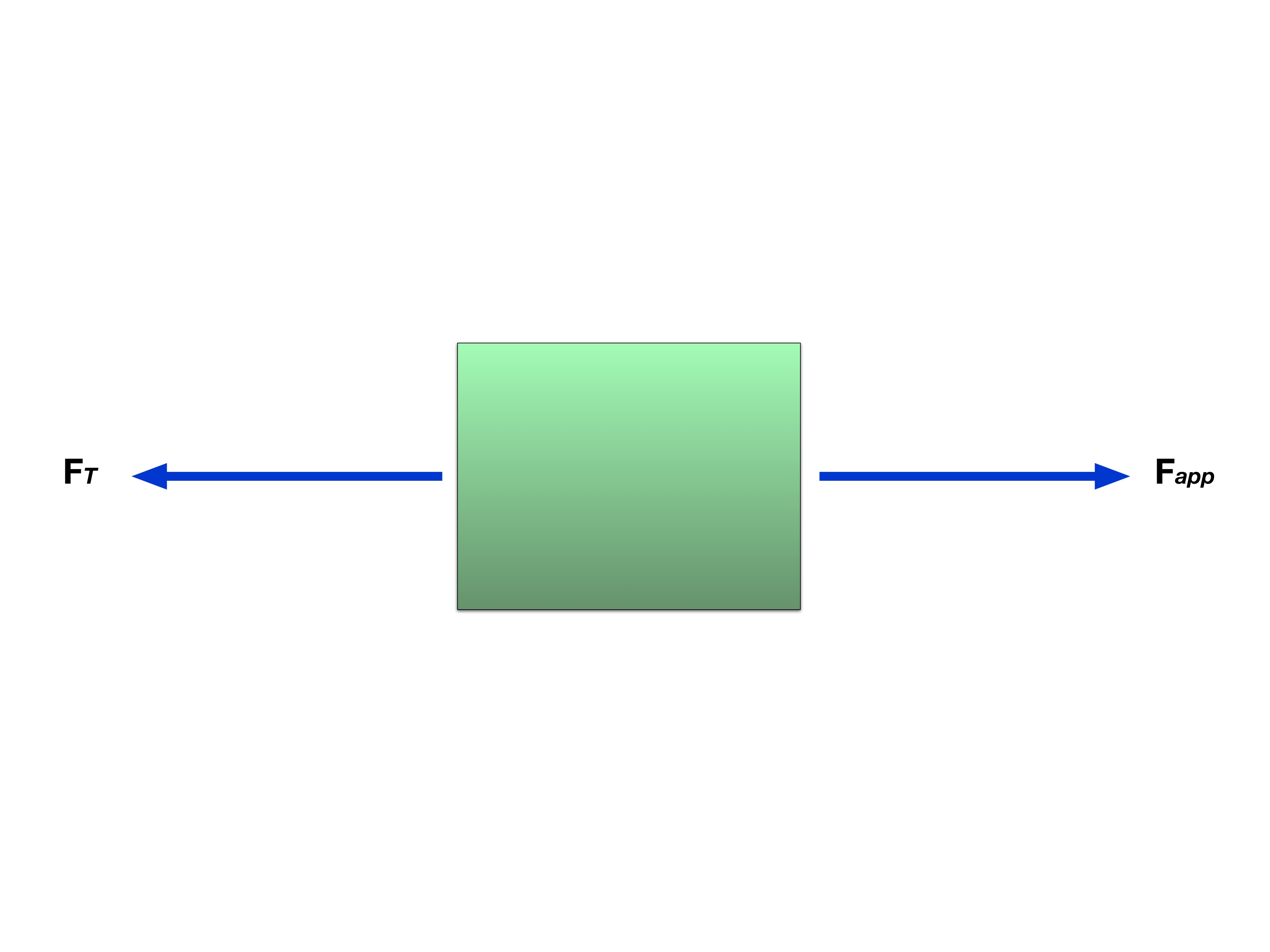
As shown by the FBD in Figure 2.2.2, the tension acts in the direction opposite to the applied force.
Key Point: Tension forces always act as pulling forces when applied to objects. A rope in tension is pulling on whatever it is being held by at both ends.
Figure 2.2.3 is an invention called the Atwood Machine. Notice how in the figure, tension acts on both sides of the pulley. And depending on the mass of each block, the system will tend to accelerate towards a certain side. Assuming there is no friction in the pulley, it makes sense then that the heavier block will pull the rope towards its respective side and accelerate downwards, while the lighter block accelerates upward.
Figure 2.2.3 Pulley: Atwood Machine
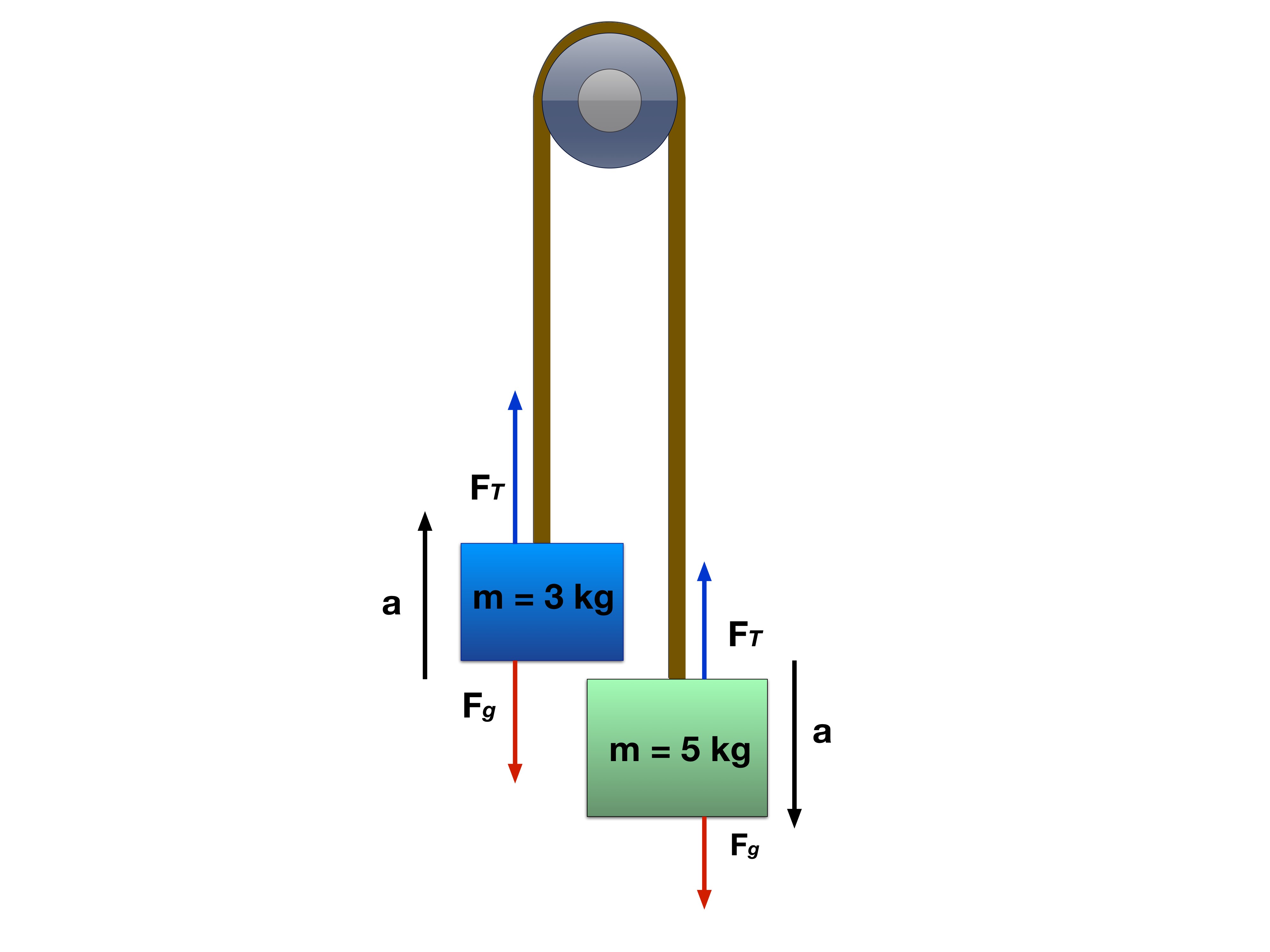
For an ideal massless rope passing over massless frictionless pulleys, tension has the same magnitude throughout one continuous rope. Different ropes need not have equal tension.
This means that in the pulley system shown in Figure 2.2.3, each depicted acting on each block provides the same force.
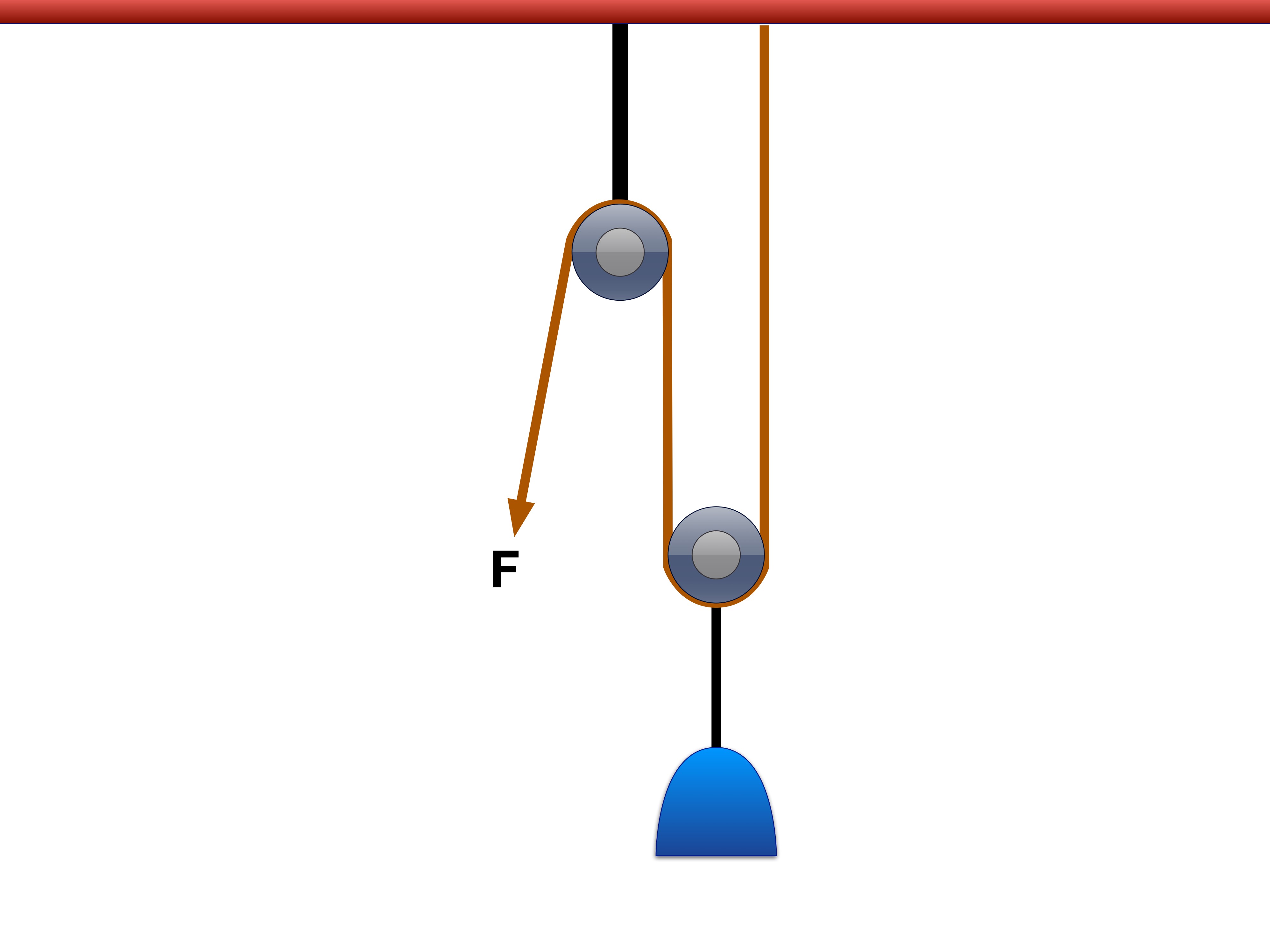
Pulleys can even ensure that the tension force is applying in the same direction on either end of the rope. Figure 2.2.4 shows how tension works in a pulley system. Notice that the tension on either side of the rope is equal in magnitude, and in line with the rope.
Real massive ropes or rotating massive pulleys can require different tensions at different points. In the following ideal-pulley model, rope and pulley masses and axle friction are neglected.
In our problems, we will ignore friction and pulley mass, however, ensuring that our pulley problems are quite a bit more easily solved.
Figure 2.2.4 The Pulley
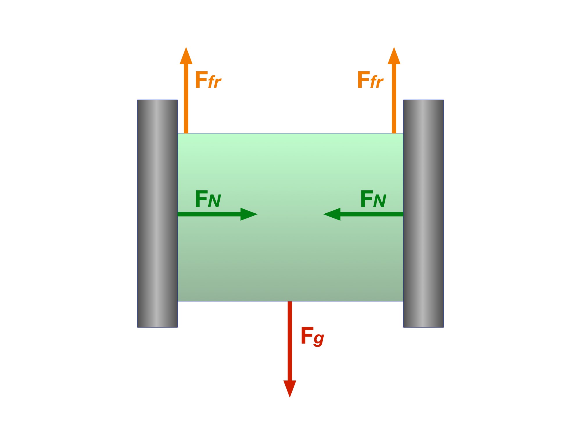
The green box is sliding down between the two walls making the friction force act in the upward direction. Notice how the friction and normal force are perpendicular to one another.
Read every step and figure
Step 1
The green box is sliding down between the two walls making the friction force act in the upward direction. Notice how the friction and normal force are perpendicular to one another.
Step 2
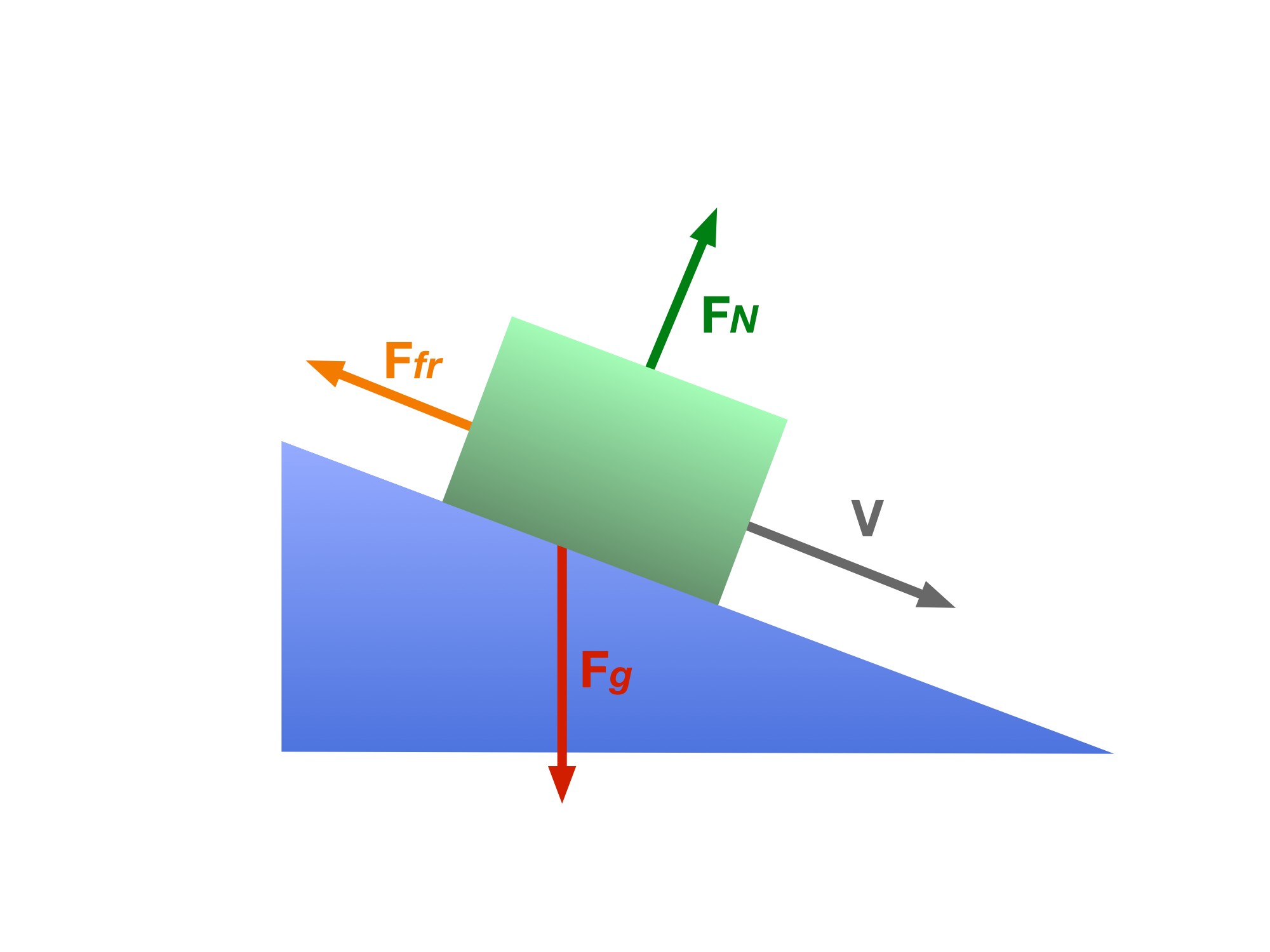
Again, box is sliding towards the right so friction acts in the opposite direction. The normal force is again shown to be perpendicular to the surface of contact and the friction force
Step 3
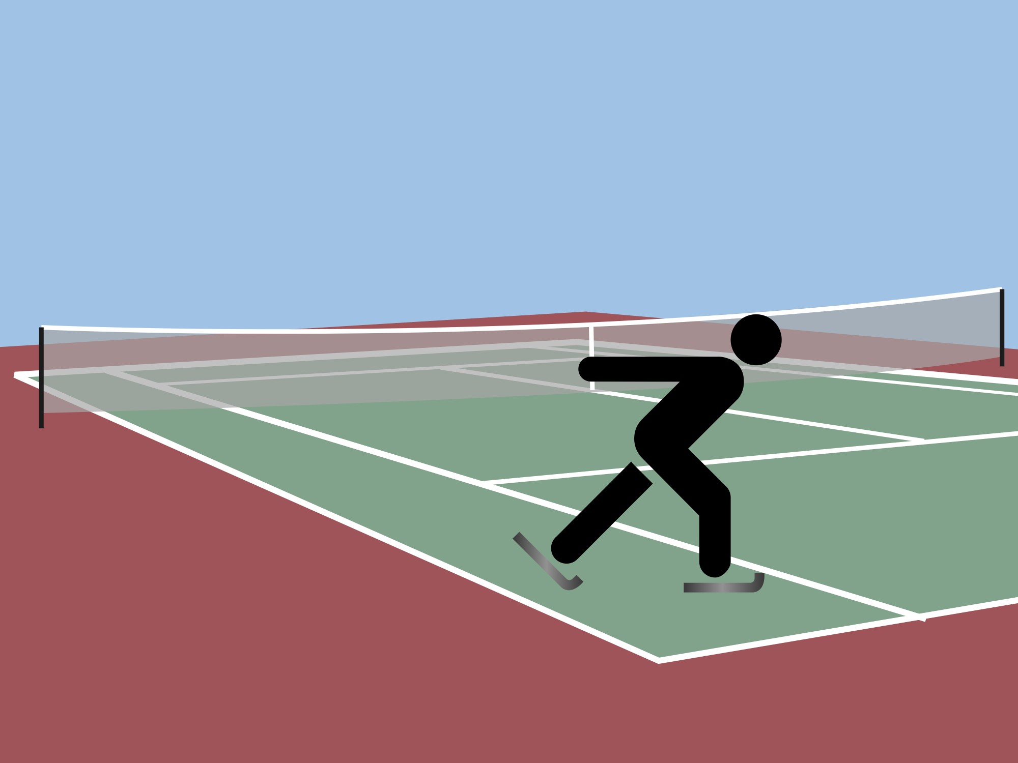
Imagine a person skating on a tennis court, not ice. It would be hard right? That’s because the friction force felt between the skates and the surface is much greater than on ice.
Step 4
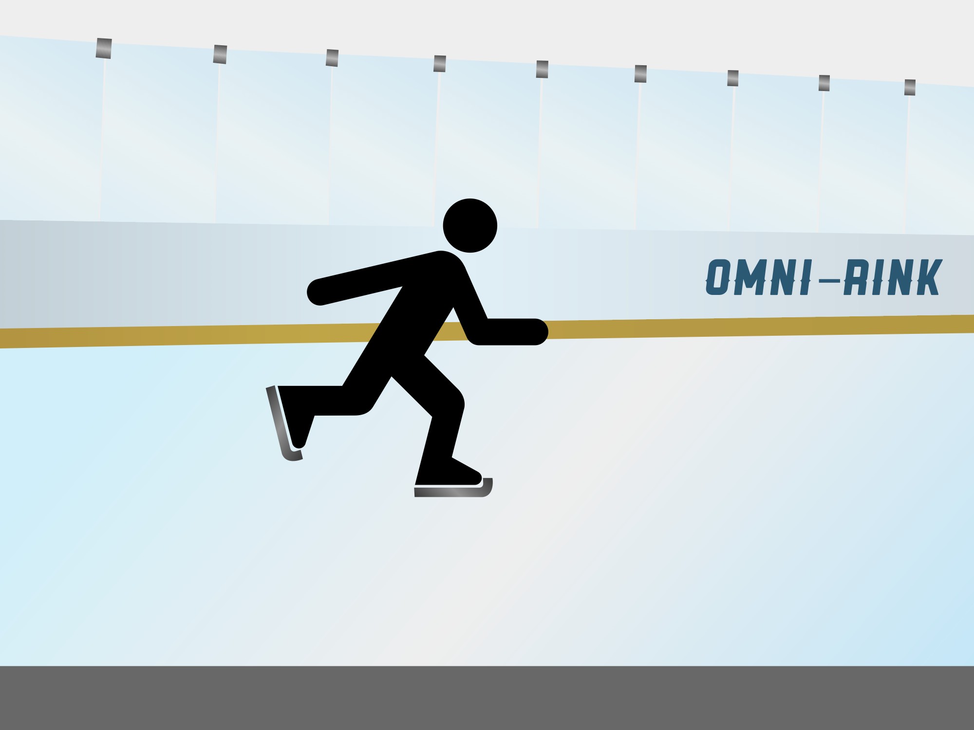
We’ve already talked about static friction in chapter 1 and brushed up on what kinetic friction is empirically, but let’s discuss the main differences between the coefficient of static friction and the coefficient of kinetic friction.
Static friction acts between contacting surfaces that are not sliding relative to one another. Its magnitude adjusts from zero up to μₛN as needed.
Kinetic friction acts during sliding at a contact, with magnitude fₖ = μₖN in this model. A braking tire that rolls without skidding generally uses static friction; a skidding tire uses kinetic friction.
The concept of weight is something we talked about in the previous section and chapter. It is the same as the force of gravity that is exerted on an object. it is represented by the force equation:
Weight is essentially how heavy or light an object is. Since it is the same as , weight is a vector with both magnitude and direction. Therefore, force of gravity can also be written as :
(Equation 2.2.1)
Now with these three forces in mind, let’s attack some harder problems than usual where all three forces are present.
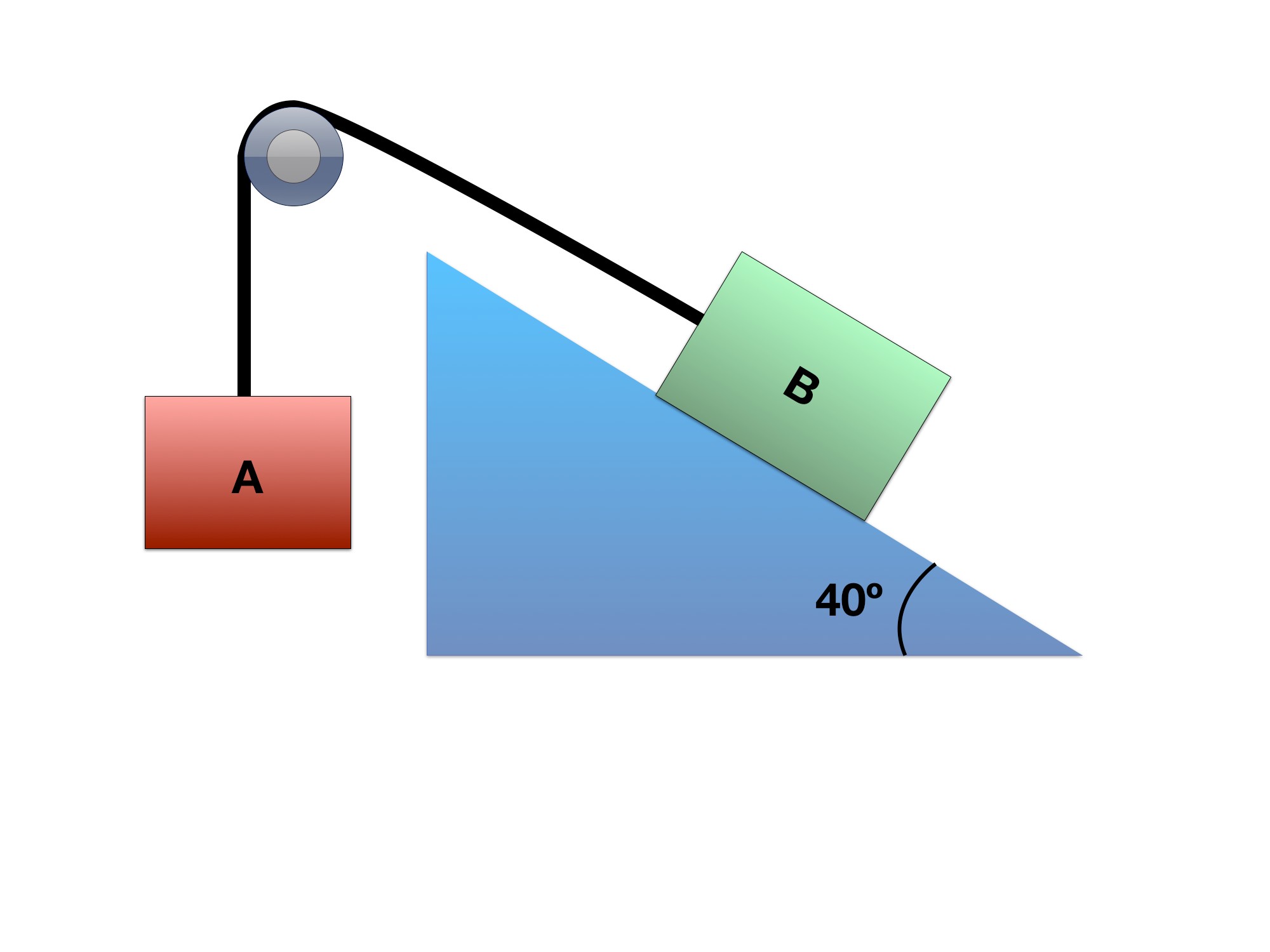
Blocks A and B, connected by a frictionless pulley.
A 4 kg hanging block A is connected over an ideal fixed pulley to an 8 kg block B on a 40° incline. Block B is currently sliding down the incline. Use μₖ = 0.3 and g = 9.81 m/s². Find each block’s acceleration and its direction.
The negative acceleration means block B accelerates uphill while block A accelerates downward. If B is currently sliding downhill, it slows; negative acceleration alone does not mean it is already moving uphill.
Block B’s acceleration is 0.569 m/s² uphill; block A’s acceleration is 0.569 m/s² downward.
Therefore:
The EOM for block B in the x direction is:
so:
and in the y- direction there is no acceleration so sum of forces in y-direction for block B is zero! Thus, we can set the normal force and the y component of the gravity force equal to each other.
Step 1: Set up your Free Body Diagram
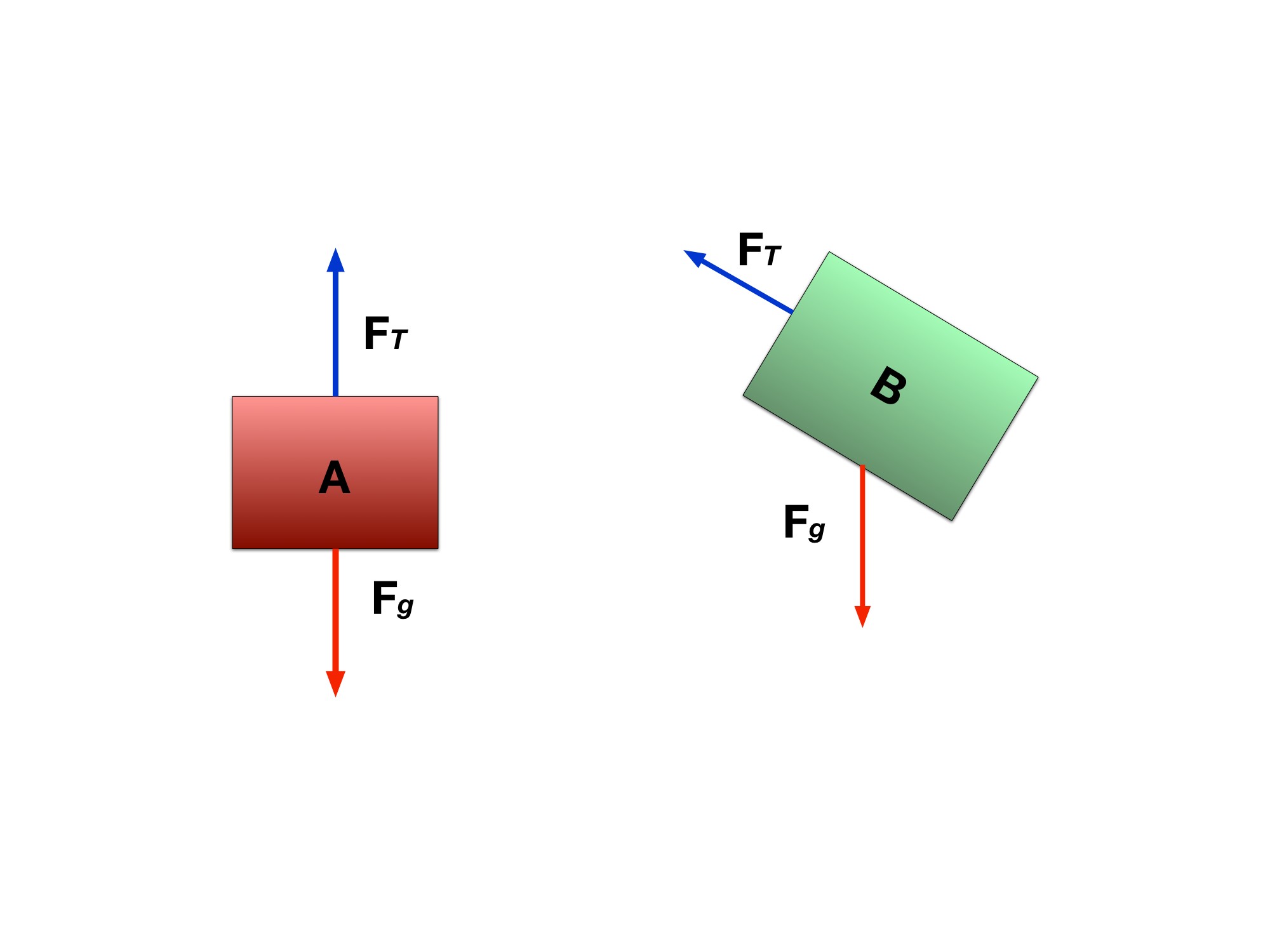
Reference the image in this Gallery to view the FBD. Notice here that there are two FBDs constructed and two reference axes, one for block A, the other for block B. Each of the reference frames are oriented in the same direction as the object. Remember that we can set our reference axes to whatever orientation we want. It’ll cause less of a headache for us when we’re setting up our equations of motion.
Step 2: Break up the forces into x and y components
Based off the FBD, let’s approach the forces that are on each block. The force breakdown can be seen in this here Gallery. For block A, we see that forces are only in the y-direction which are tension and the weight of block A.
According to the reference axes for block A, the weight is acting in the negative y-direction so:
For block A, T − m_Ag = m_Aa, with upward positive. For the currently downhill-sliding block B, the shared signed acceleration is a = −0.56915 m/s².
Notice how the acceleration is negative. Due to our reference axes, we are assuming that a positive movement would be block B moving down the plane and pulling block A up.
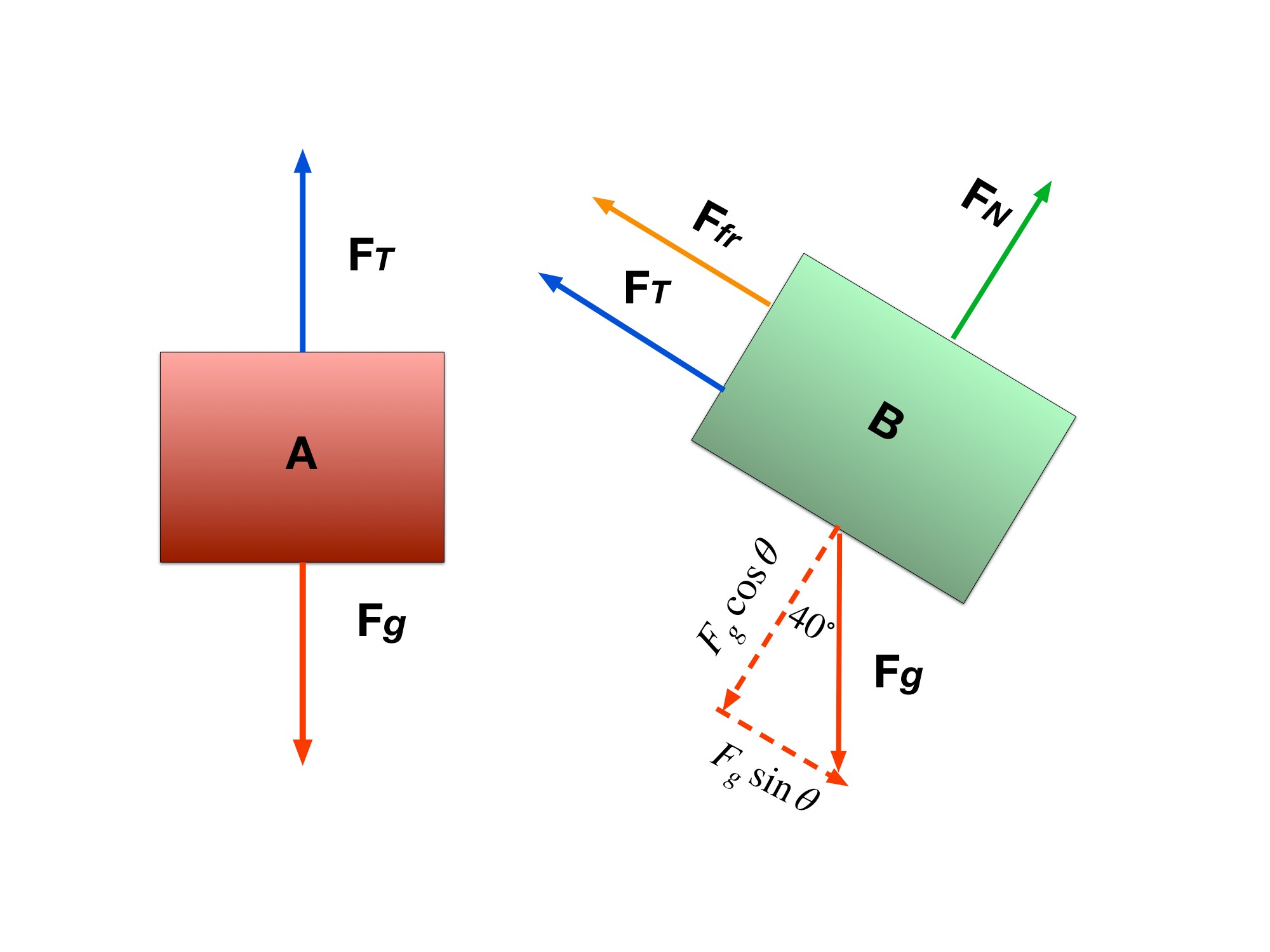
Here are the more detailed FBDs for each block. Friction, the normal force, and the gravity components are added.
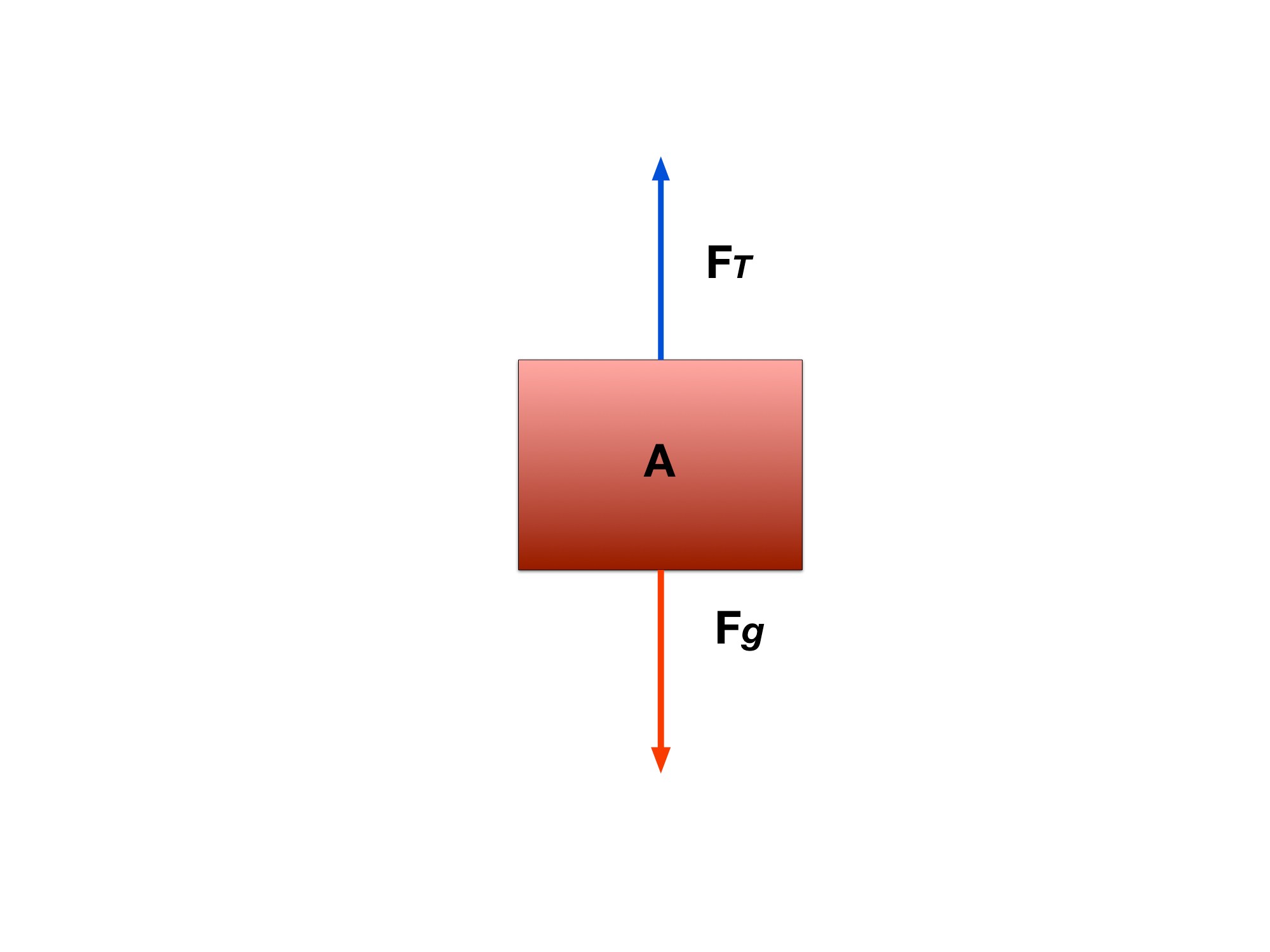
y-components for block A.
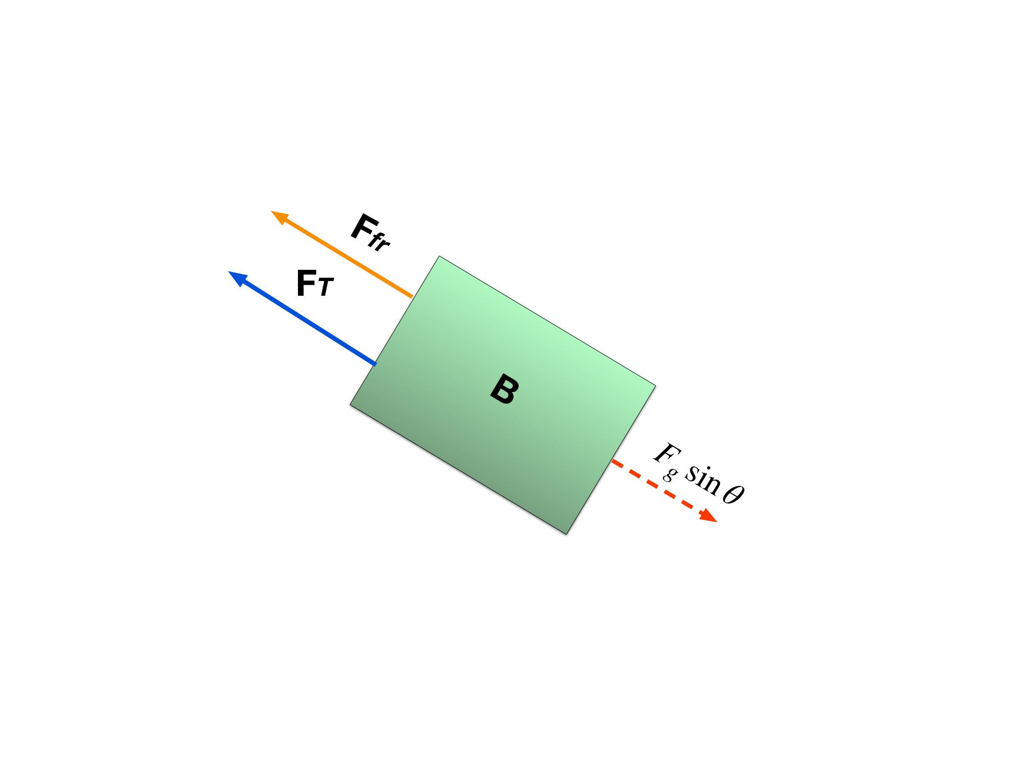
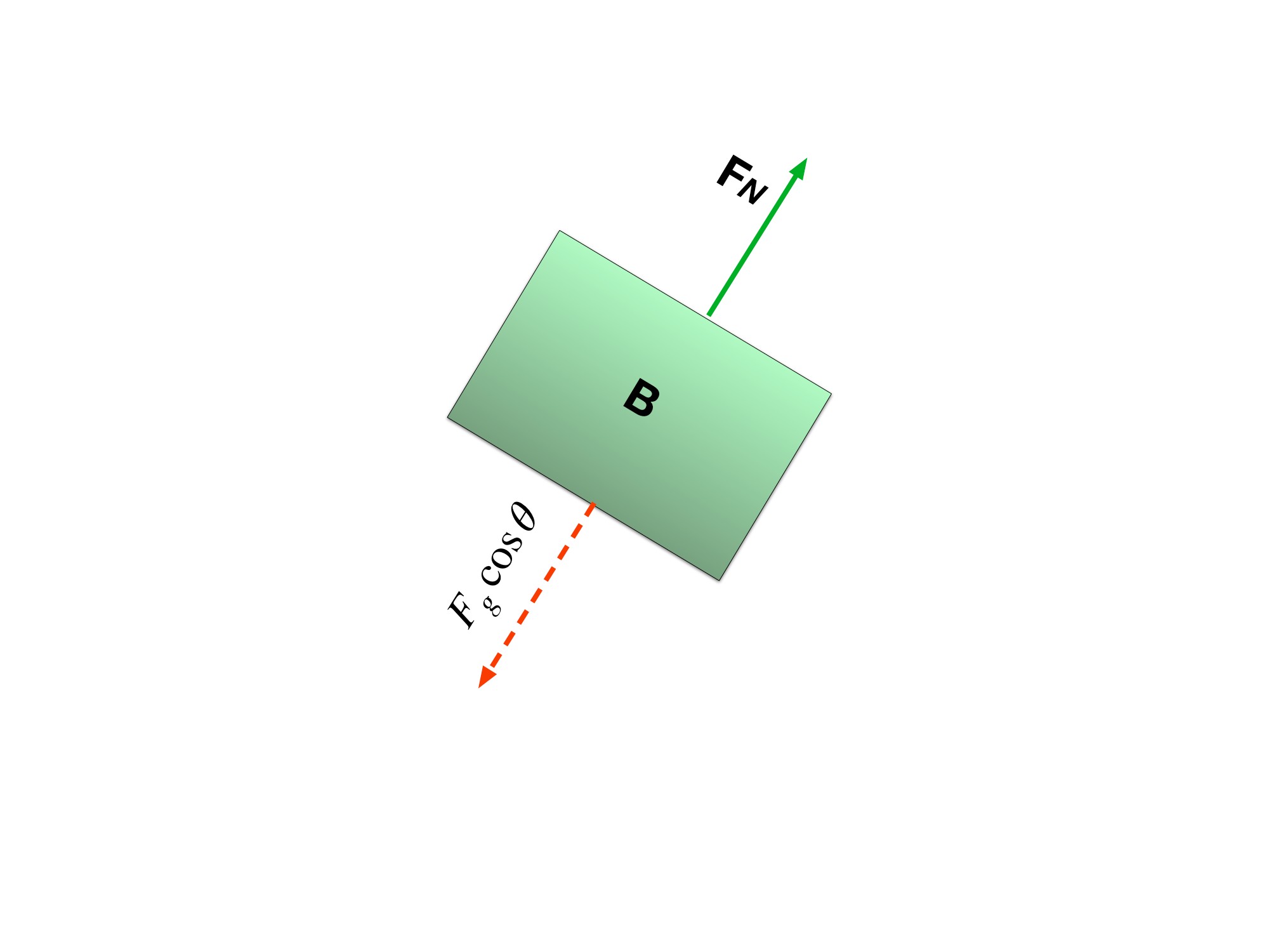
Notice how the Tension force is represented by just T for both blocks A and B. This is because we are concerned with how the system as a whole is accelerating so the tension force that is present in block A is the same as the tension force felt in block B. so we can rewrite the x-component of the force balance as:
and combine all the equations to get:
Step 4: Solve for the acceleration of the system
The rope constrains the two blocks to have equal acceleration magnitudes along their respective paths. Their acceleration vectors point in different spatial directions.
Example Problem 2.2.2
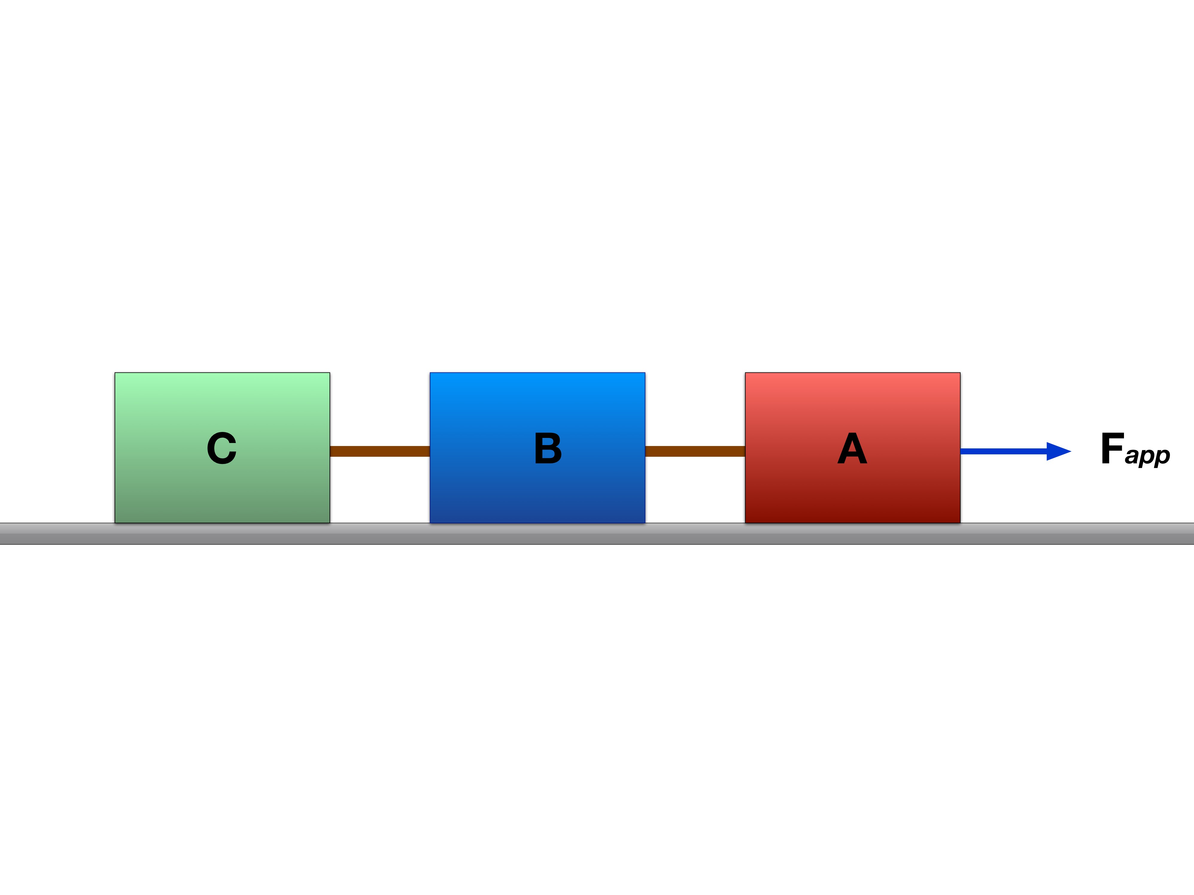
Blocks A, B, and C are connected to each other. Block A is being pulled to the right with a force F. You know that the surface is frictionless, all blocks have mass , and that the tension between blocks A and B is . Determine the acceleration of the blocks.
Step 1: Determining approach to the problem
To solve this problem, we first have to notice that since blocks B and C are not moving with respect to each other we can treat them as on “large” mass (i.e mass of block B + mass of block C.
Let’s call this large mass block D. The tension of between blocks A and B then acts as the only force on this combined mass system.
Step 2: Draw our FBD for the block D
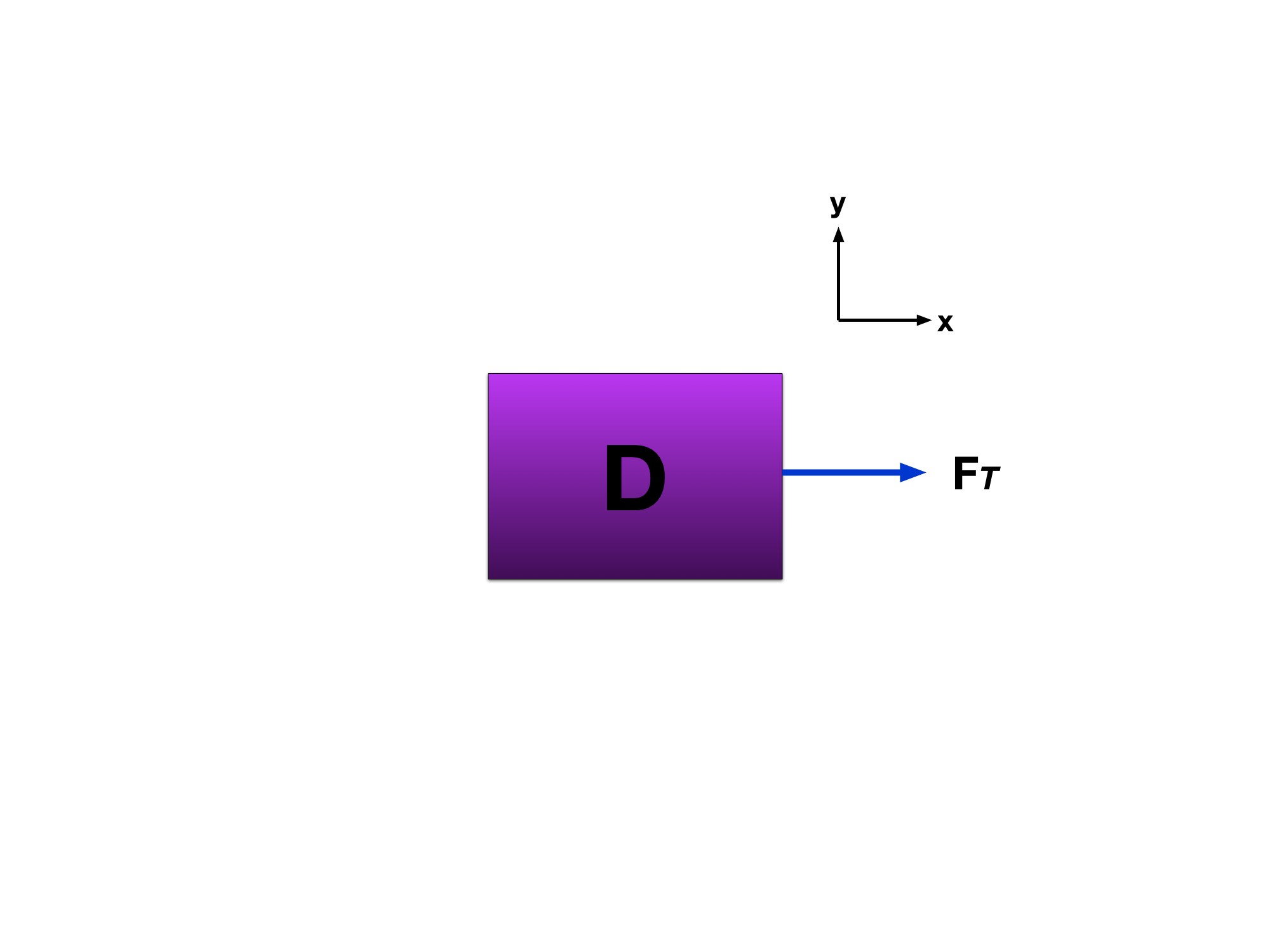
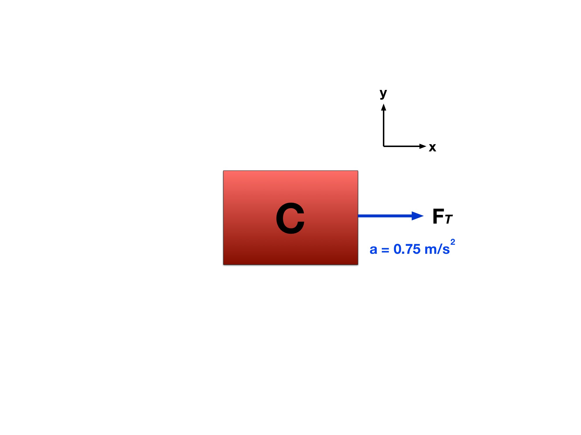
Look at the second image in Gallery 2.2.2 to view the FBD. Notice here how we did not include block A in the FBD. Well it wouldn’t help us solve our problem since it doesn’t affect block D.
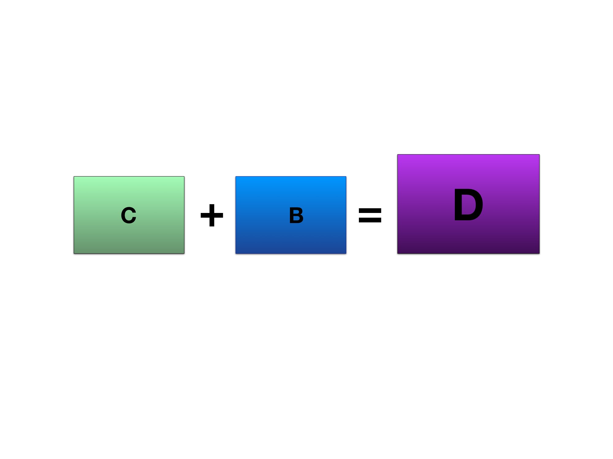
Block D represents the mass of blocks B and C. Block D will help us in solving for the acceleration for both blocks C and B
Step 4: Solve for the acceleration of block D
Since we can treat blocks B and C as one, then we can assume that they both have the same acceleration. In the mean time, let’s solve for block D’s acceleration. Using the force balance equation, we can find the acceleration:
We know our only force is tension and that the mass of block D is mass of both blocks B and C. Let’s use that information to redo our equations.
Remember that the tension force of on block D is the tension force between blocks A and B originally. View Figure 2.2.3 to see original diagram.
Pop Quiz 2.2.1 Common Forces
Question 1 of 5 · 0 correct
AP Topic 2.7 · Read the worked solution
A 3 kg box is pushed parallel to a 20° incline, uphill at constant speed. The kinetic friction coefficient is 0.4. What push is required? Use g = 9.81 m/s².
Read every full question without answers
Question 1
Question 2
If a man pulls on a (currently stationary) block as shown, which of the following values for the applied force will slide the block along the ground without lifting it, if the relevant friction is ?

Question 3
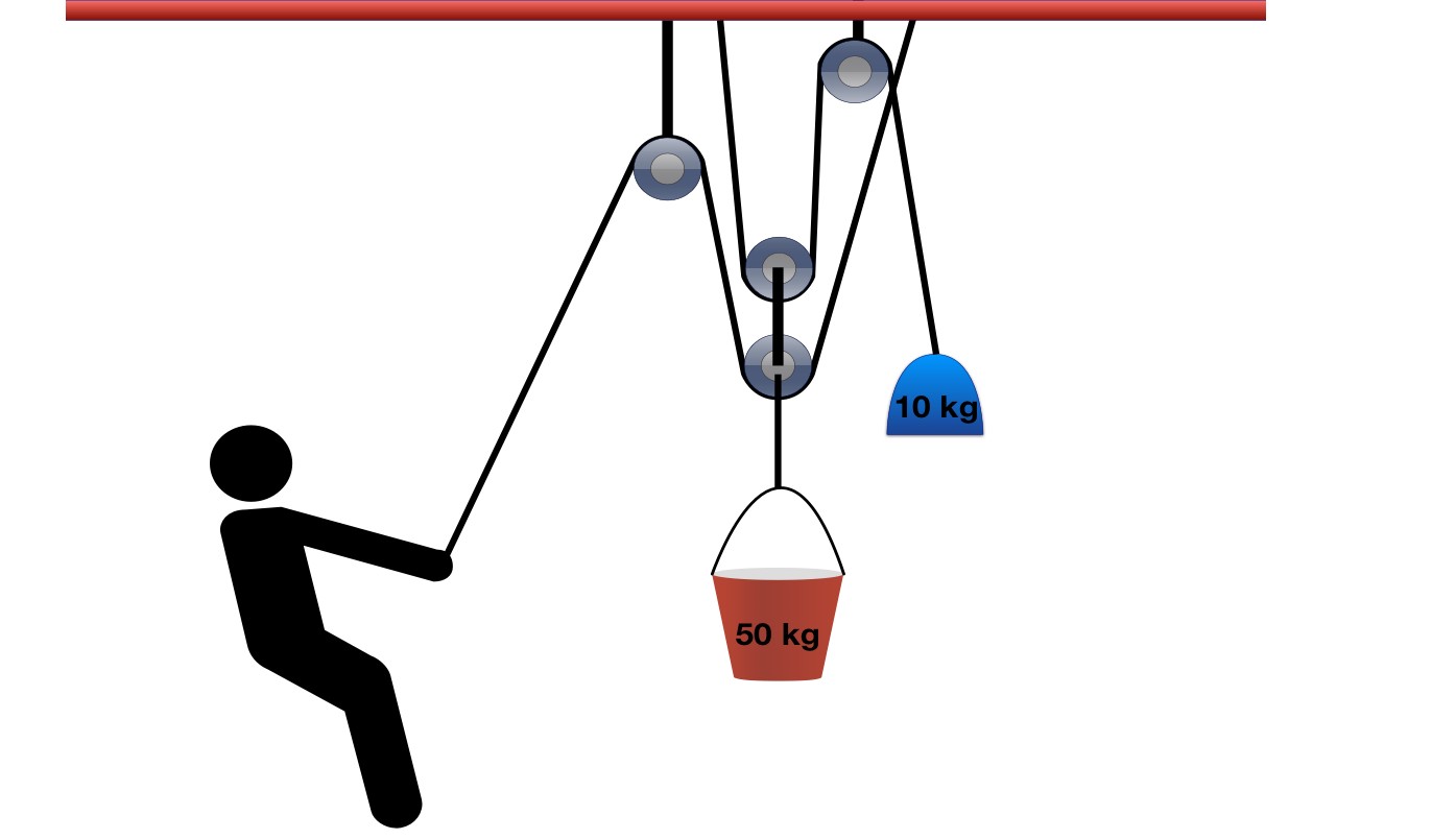
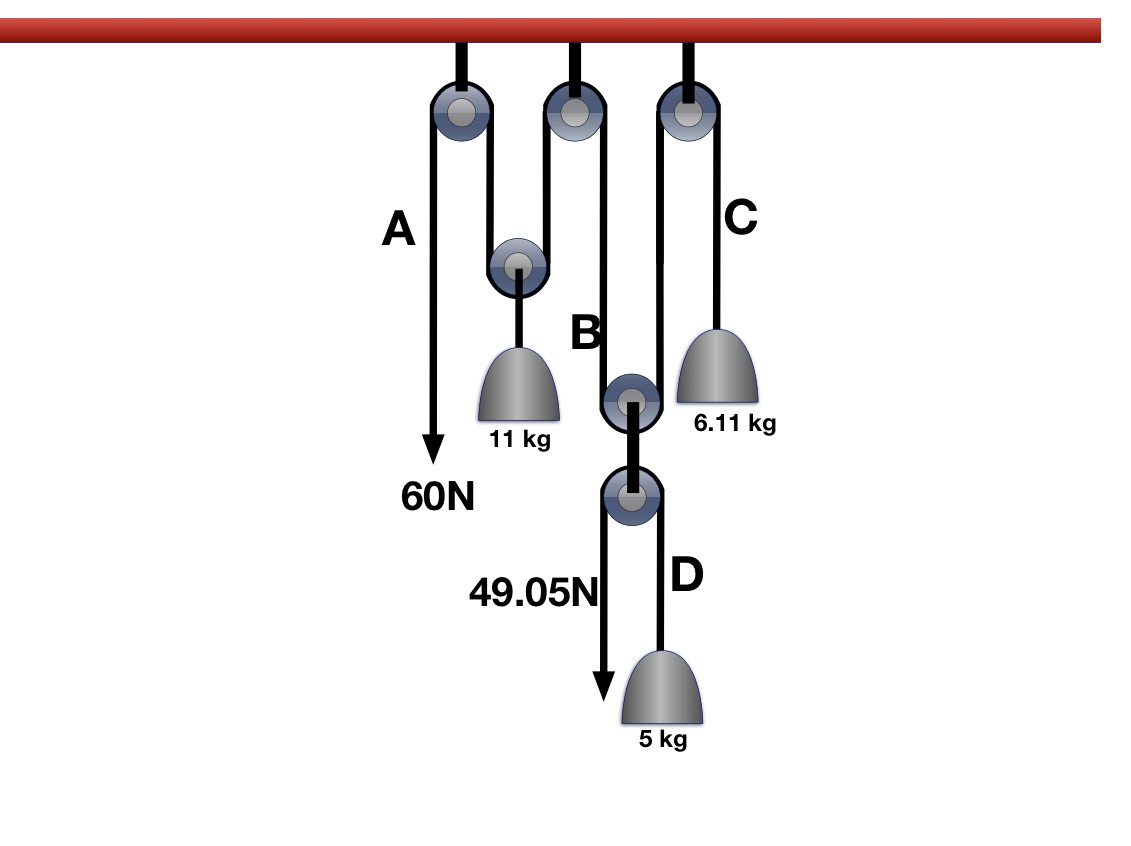
A construction worker raises the 50 kg bucket shown using a 10 kg counterweight. Treat the pulleys and ropes as ideal, with two vertical support segments at each movable pulley. What downward pull is required for steady lifting? Use g = 9.81 m/s².
Question 4
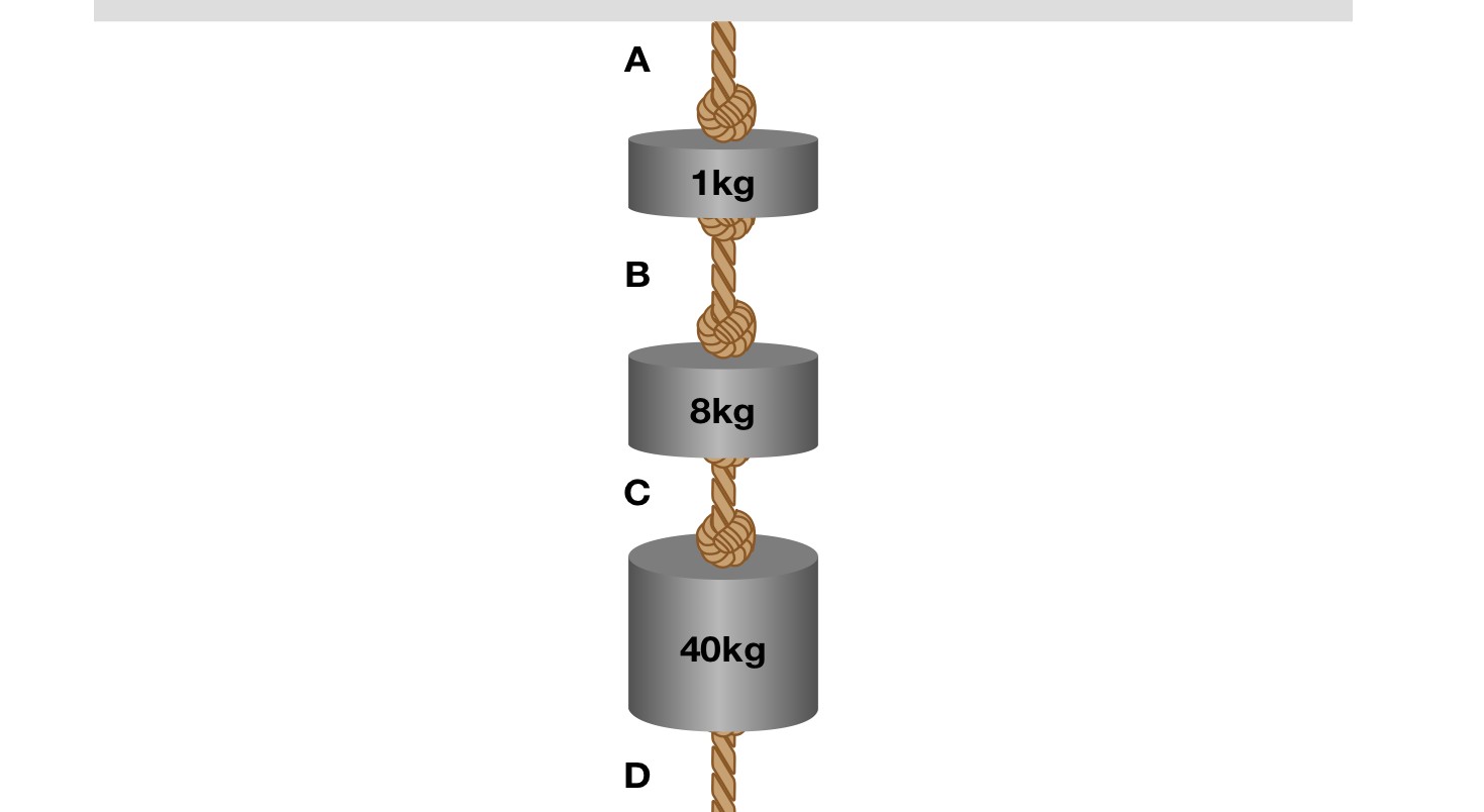
Three weights are tied together and suspended. Another weight is added. If the rope can only support of tension, which length of rope snaps first?
Question 5


Reviewed physics notes (12)
These corrections keep the original lesson’s purpose while fixing errors in the source edition.
- Uniform tension requires an ideal-rope model. — Reference 1
- Mass is not changed by tension; different tensions can provide the torque for a massive pulley. — Reference 1
- Static friction can act on a moving but non-sliding object. — Reference 1
- Braking does not automatically mean kinetic tire-road friction. — Reference 1
- An applied force merely exceeding instantaneous rope tension does not itself imply rupture. — Reference 1
- Equal scalar magnitudes do not mean identical vectors. — Reference 1
- Use a consistent signed rope coordinate. — Reference 1
- The source equates acceleration direction with current motion. — Reference 1, Reference 2
- Correct the inconsistent downward label for the ramp block. — Reference 1
- The source text says 300 N while the diagram says 50 kg; the keyed 147.2 N corresponds to the diagram. — Reference 1
- The source leaves the applied-force direction and acceleration unspecified. — Reference 1
- The source prompt places both blocks on the incline and says B accelerates right, while its worked diagram and signed equations describe a hanging block and downhill sliding. Specify the actual geometry and sliding direction without prejudging acceleration. — Reference 1, Reference 2
Glossary and deeper reading · 8 refreshers
These editorial refreshers supplement the reading. Definitions and examples are added guidance; original source wording and recorded answers remain in their original context.
-
Force
A force describes an interaction that can change an object’s momentum. It is a vector measured in newtons, so both size and direction matter when forces are added. For example, a rope can pull a cart while the floor exerts friction in another direction.
-
Tension
Tension is a pulling force transmitted through a stretched rope, string, or similar connector. It acts along the connector away from the object it pulls, and an ideal massless rope has the same tension throughout an uninterrupted segment. For example, a rope supporting an accelerating load can have a tension different from the load’s weight.
-
Free-body diagram
A free-body diagram shows the external forces acting on one selected object or system. Each arrow names a real interaction, and its direction is the direction of that force. For example, a book resting on a desk has a downward gravitational force and an upward normal force; velocity is not an extra force arrow.
-
Magnitude
Magnitude is the nonnegative size of a vector quantity. It does not specify direction, and it differs from a signed component. For example, a westward velocity can have a negative x component while its speed, the velocity magnitude, stays positive.
-
Coefficient of friction
A coefficient of friction is a dimensionless parameter describing friction between a pair of surfaces in a specified model. The static coefficient sets a maximum friction magnitude, whereas the kinetic coefficient models friction during sliding. For example, changing a shoe’s material or the floor condition can change the coefficient without changing the shoe’s mass.
-
Weight
Weight is the gravitational force exerted on an object by a specified attracting body. Near Earth’s surface its magnitude is approximately mass times the local gravitational field strength, and it is measured in newtons. For example, an astronaut has less weight on the Moon while retaining the same mass.
-
Gravity
Gravity is the attractive interaction between masses in the Newtonian model. For spherical bodies or point-mass approximations, its strength decreases with the square of the separation between their centers. For example, Earth’s gravity provides the inward force that keeps a satellite in orbit.
-
Vector
A vector is a quantity with a magnitude and a direction, represented by an arrow or by components along chosen axes. Vectors add by adding corresponding components rather than simply adding their magnitudes. For example, an eastward displacement followed by a northward displacement produces a resultant pointing northeast. The zero vector has zero magnitude and no unique direction.