Moment of Inertia
Original textbook reading.
The point-mass, rigid-body and parallel-axis worked examples are useful AP instruction. Calculus derivations and the complex composite rocket are extra exploration; the corrected model is retained.
For rotational acceleration about a specified fixed axis, the required net torque depends on both the mass distribution and the axis through the moment of inertia.
If you have two objects, a pencil and a ball with the same mass, and you try spinning them, spinning the pencil around its center similar to a plane’s propeller, you might notice that the pencil takes more force to get it to spin the same that the ball does.
That doesn’t make sense, as they are the same mass, so the same force should induce the same type of motion on the object, right?
Actually, in terms of rotating objects, it is not the masses that have to be equal, but the moments of inertia.
Figure 6.2.1 Moment of Inertia
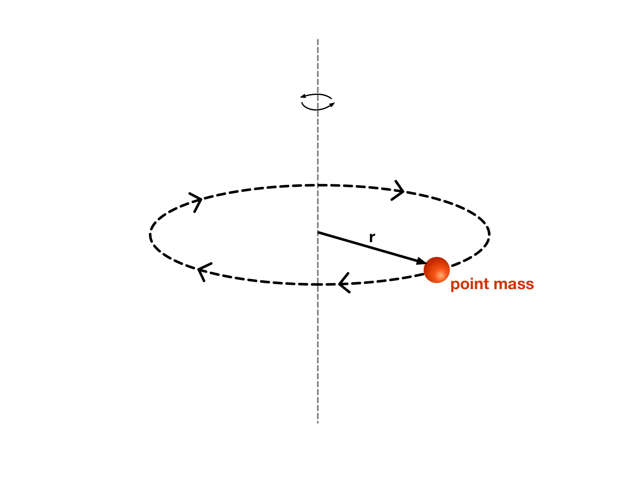
Moment of inertia describes how mass is distributed relative to a chosen axis. Bodies with the same moment of inertia about that axis have the same angular acceleration when acted on by the same net torque: α = τ_net/I.
The simplest form of inertia is a point mass revolving around a given axis. For the point mass, the moment of inertia is given as:
In I = mr², r is the perpendicular distance of the point mass from the rotation axis. For extended bodies, the inertia depends on every mass element’s distance from that same axis.
This question is only fully answered through the use of calculus, and it goes into the idea behind a moment of inertia.
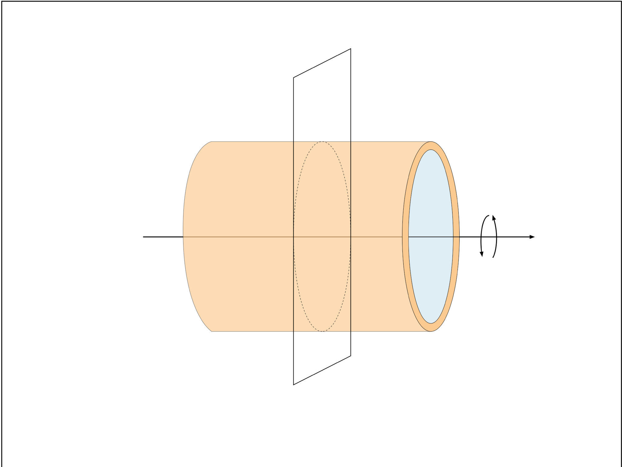
Step 1: Identify the axis. The shell rotates about the line through the centers of its circular ends, along its length. The slicing plane is perpendicular to that axis and exposes a ring-shaped cross-section.
For an ideal thin wall, all its mass lies at the same perpendicular distance r from this axis. A transverse rotation axis would be a different problem.
Read every step and figure
Step 1
Step 1: Identify the axis. The shell rotates about the line through the centers of its circular ends, along its length. The slicing plane is perpendicular to that axis and exposes a ring-shaped cross-section.
For an ideal thin wall, all its mass lies at the same perpendicular distance r from this axis. A transverse rotation axis would be a different problem.
Step 2
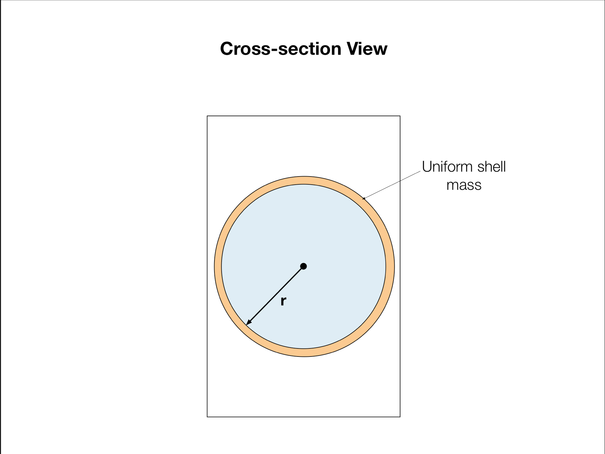
Step 2: Locate the mass. The orange ring is the shell’s material. The blue interior is empty; it contributes no mass. The marked radius r is the perpendicular distance from the central axis to the thin wall.
Step 3: Add the contributions. Each small mass contributes r²dm, so I = r²Σdm = mr² about this central longitudinal axis. This thin-shell result is not the ½mr² result for a solid cylinder. Moment-of-inertia reference.
This shell has no deviation in its mass distribution around the axis of rotation, as it is of uniform density and its mass is only present at a constant distance from its axis.
As you can see in the picture, the cross section of the object is a pure circle. Therefore the only mass will always be a distance of from the center of rotation.
This means that the integral can be simplified by declaring and to be constants:
This becomes:
As density is given as:
But of course, non-Calculus students will find it easier just to work with the following tables. Trust us, we prefer to use these tables too, and it will save you a lot of headaches.
We can say that:
Now we need to figure out what is equivalent to. As measures the distance between the axis of rotation and the mass, is the radius of the shell, . Using that, we find that we can fully define the moment of inertia of a shell rotating as shown to be:
Now this is for a shell with a constant radius. Things change when you have weird mass shapes with varying radii.
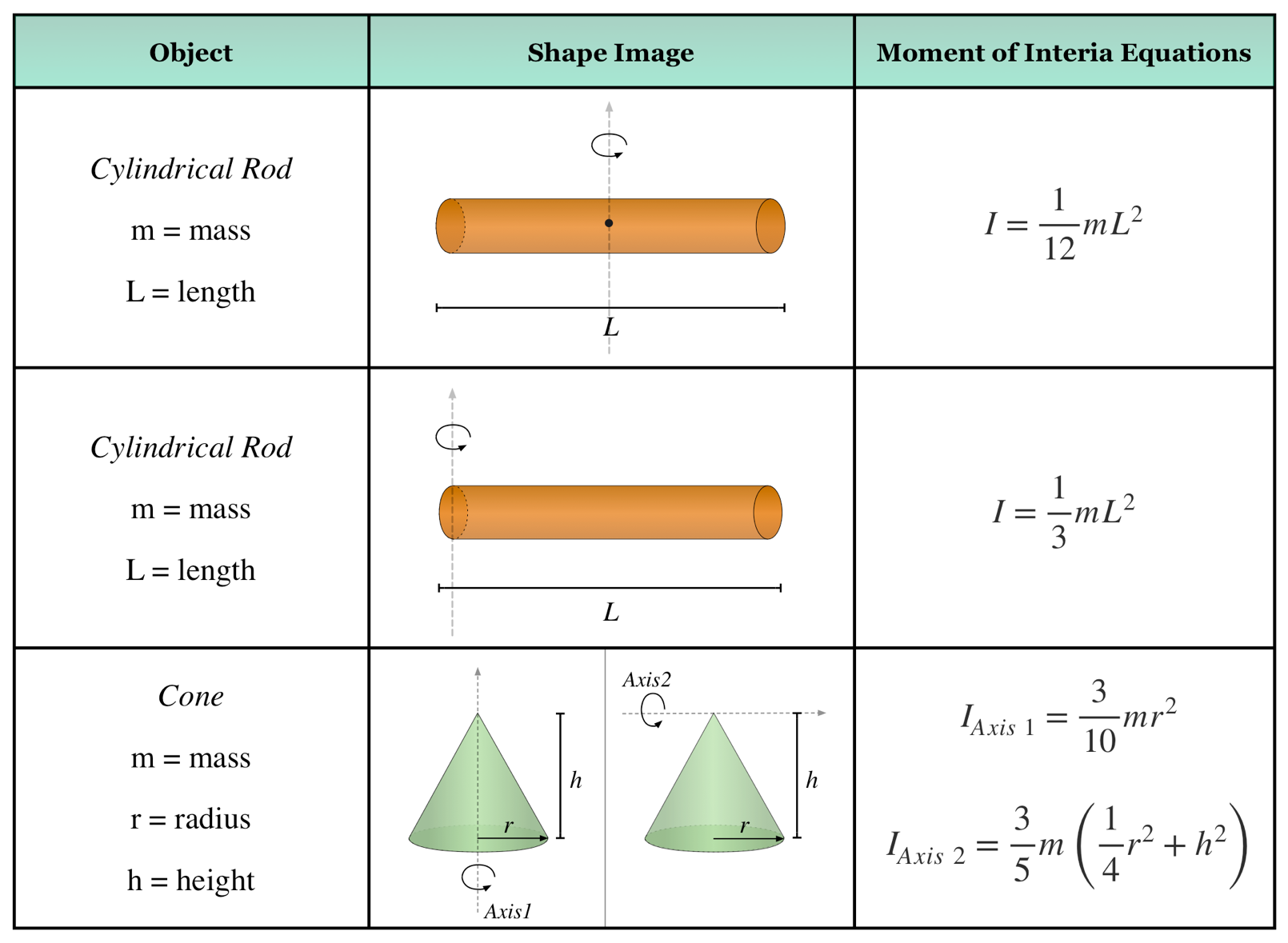
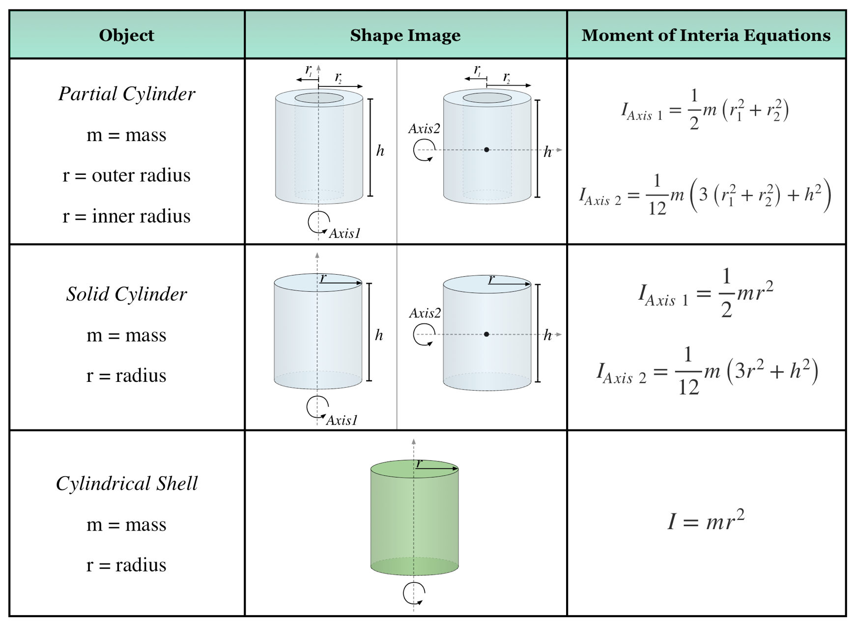
| Object | Rotation axis | Moment of inertia |
|---|---|---|
| Thin uniform disk | Axis 1: through center, perpendicular to disk | ½mr² |
| Thin uniform disk | Axis 2: any diameter in disk plane | ¼mr² |
| Thin hoop | Axis 1: through center, perpendicular to hoop | mr² |
| Thin hoop | Axis 2: any diameter in hoop plane | ½mr² |
| Thin spherical shell | Any diameter | ⅔mr² |
| Uniform solid sphere | Any diameter | ⅖mr² |
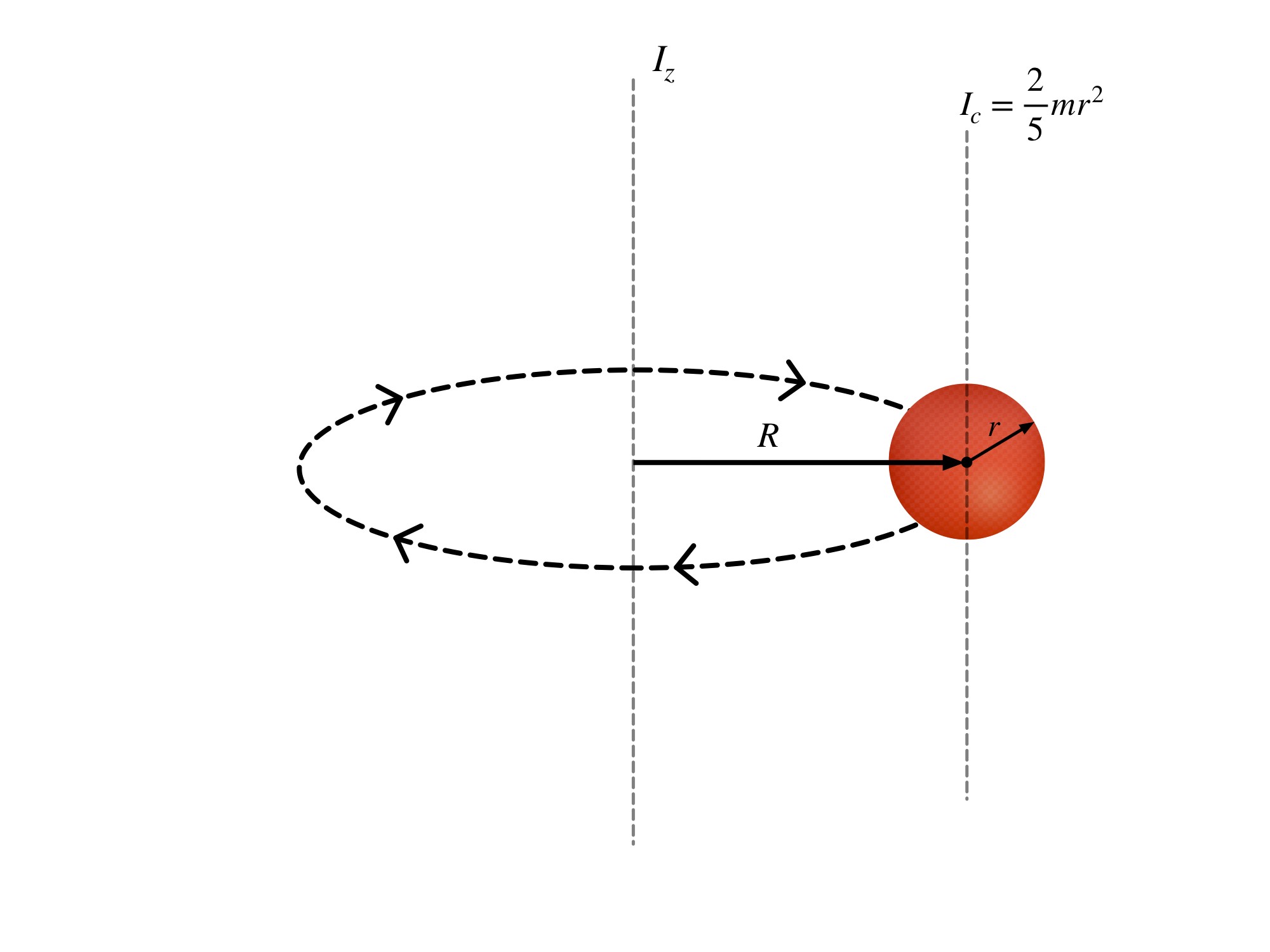
While that might be simple, what if a situation arises where you have to find the moment of inertia of an object, but the axis it is rotating around is not through the center of the object. For example, say you had a ball on a string attached to a pole and you wanted to find the moment of inertia of the ball as it rotated about the pole.
In this case, you can’t just use the equation , as that only applies to the ball rotating about its center. Instead, you have to apply the so-called parallel-axis theoremⓘ.
Pop Quiz 6.2.1 Moment of Inertia
Question 1 of 5 · 0 correct
AP Topic 5.4 · Read the worked solution
The object rotates about the axis shown. Its parameters are given in the image. What is the moment of inertia?
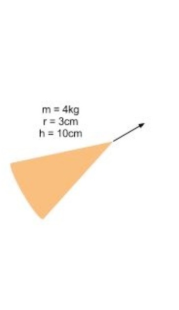
Read every full question without answers
Question 1
The object rotates about the axis shown. Its parameters are given in the image. What is the moment of inertia?
Question 2
The object rotates about the axis shown. Its parameters are given in the image. What is the moment of inertia?
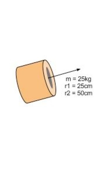
Question 3
The object rotates about the axis shown. Its parameters are given in the image. What is the moment of inertia?
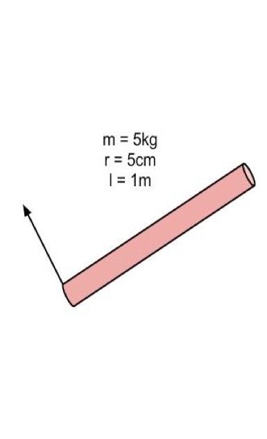
Question 4
Question 5
The parallel-axis theorem helps to convert the axis of rotation for an object. The theorem is defined as:
The refers to the new axis of rotation in question, and the refers to the axis that is parallel to the -axis, but runs through the object’s center of mass. Finally, represents the distance between the axes.
Example Problem 6.2.1
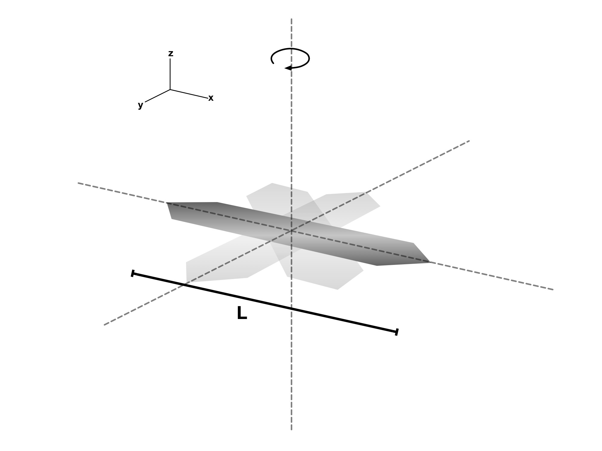
Figure 6.2.2 Parallel Axis Theorem With a Solid Ball
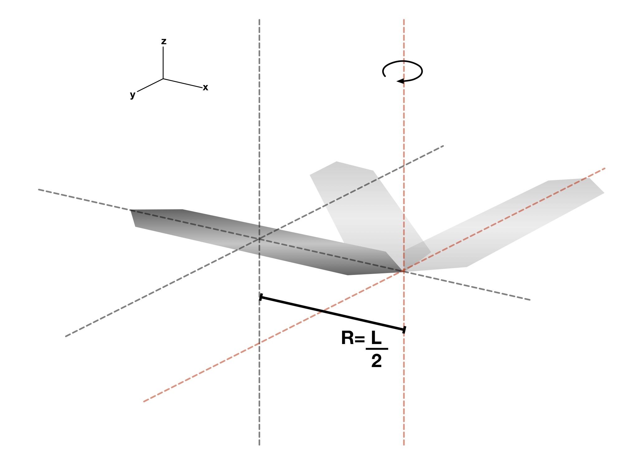
Derive the moment of inertia of a fan blade of mass and length at the end of the rod assuming that it is first rotating at the center. Assume the fan blade can be represented by a thin rod.
Step 1. Find the moment of inertia through the central axis
For this problem, we are looking at the moment of inertia of a thin rod. From the table, we find that this can be given as:
Step 2. Using the Parallel-Axis Theorem, solve
Now that we have an , we can plug that into
the parallel-axis theorem:
In this case, is the distance from the center of the rod to the end of the rod. That distance is:
Example Problem 6.2.1 Parallel Axis Theorem
Now that is a very useful formula, and it allows us to solve more complicated problems.
The easiest way to use this idea in a complicated environment is to determine the moment of inertia of an object that is not one single shape, but composed of multiple shapes.
Let’s do an example problem to show how this works, and something similar as to what you’ll see on an exam.
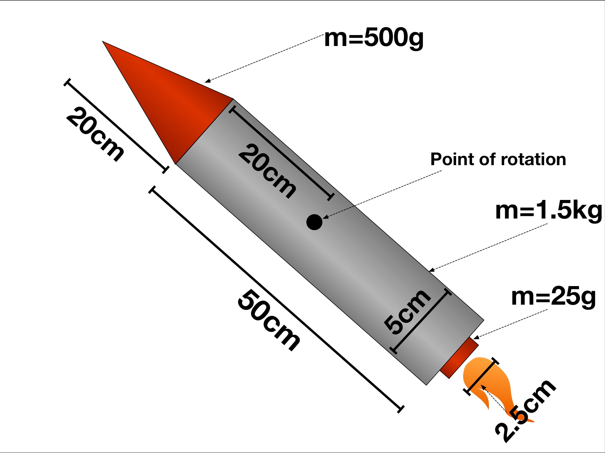
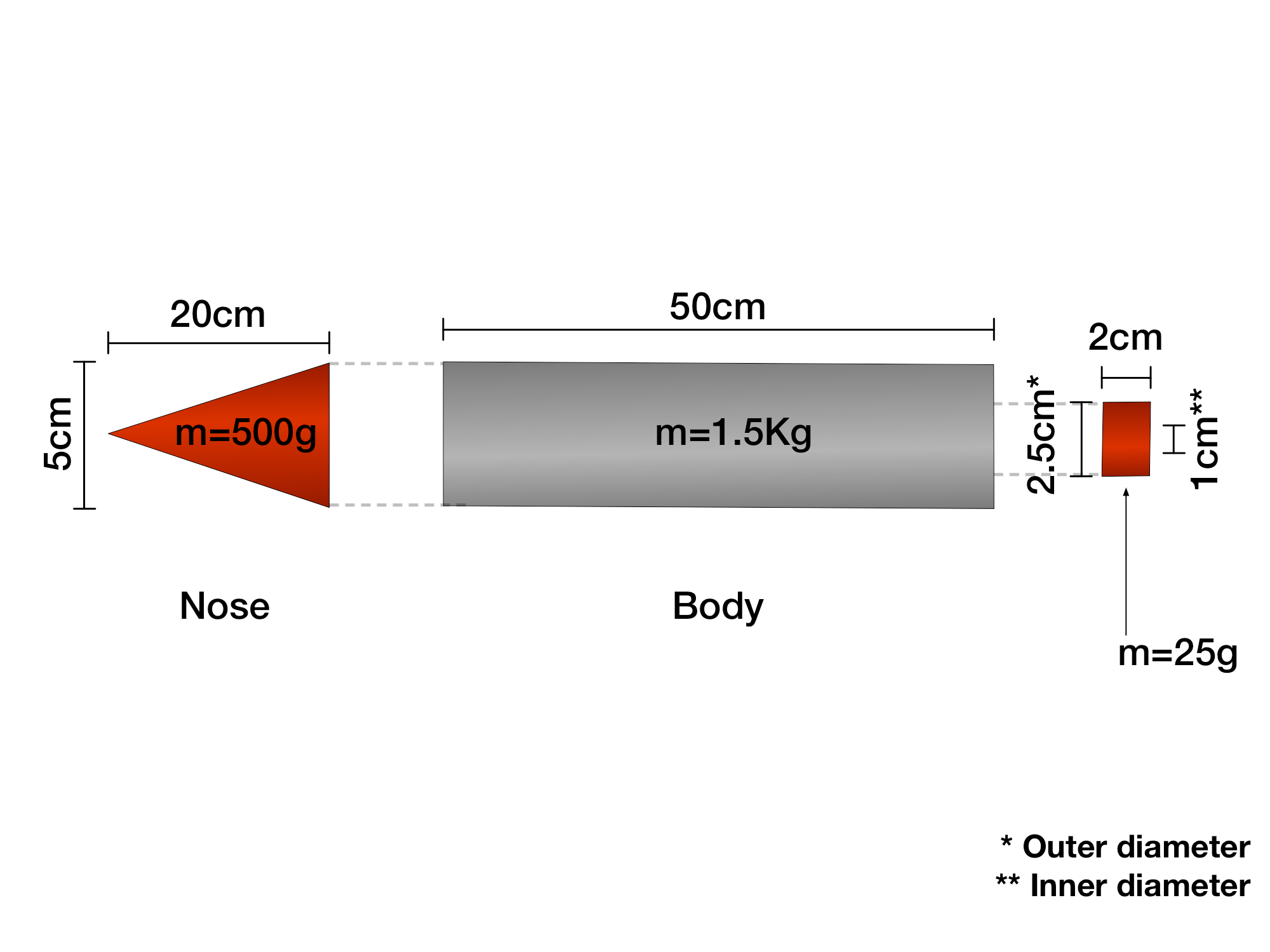
The rocket is made up of multiple shapes that each have a different moment of inertia, so we’re gonna break it down into individual shapes
Example Problem 6.2.2 3D Axis of Rotation
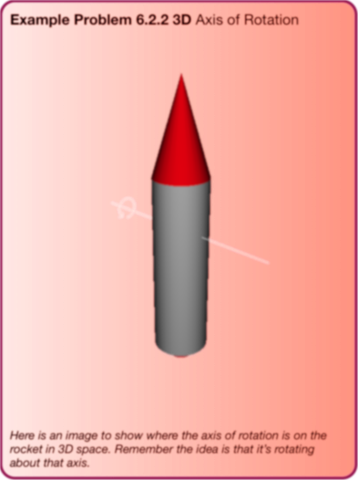
Rocket axis and components
Move the transverse rotation axis and compare each part’s contribution. The source axis is 0.20 m below the top of the body.
| Part | ICM (kg·m²) | |d| (m) | md² (kg·m²) | I (kg·m²) |
|---|---|---|---|---|
| Nose cone | 0.000937500 | 0.25 | 0.0312500 | 0.0321875 |
| Body | 0.0321875 | 0.05 | 0.00375000 | 0.0359375 |
| Exhaust | 0.00000536458 | 0.31 | 0.00240250 | 0.00240786 |
The cone and body have radius 0.050 m. The exhaust is an annular cylinder with inner radius 0.010 m and outer radius 0.025 m. Each part is uniform. The source cone formula refers to its tip; first convert it to the centre of mass, then shift to the chosen transverse axis.
If a rocket is launched, but then fails and begins to spin around the axis shown in the picture, what is the rocket’s moment of inertia for that scenario? Assume the rocket’s nose has a mass of , the body has a mass of , and the exhaust tube has a mass of .
Step 1. Identify the components of the rocket.
The rocket can be split up into the nose cone, the rocket body, and the exhaust tube.
The nose cone can be approximated as a solid cone, the rocket body will be thought of as a solid cylinder, and the exhaust tube will be labeled a partial cylinder.
Step 2.Determine the MOI for each component
Use a transverse axis through each component’s center of mass, parallel to the rocket’s red rotation axis. The cone diagram shows an apex axis, so convert its inertia to the centroid axis before applying the parallel-axis theorem.
For a uniform solid cone, I_CM = (3/20)mr² + (3/80)mh². Its center of mass is 3h/4 from the tip. The apex-axis value is I_tip = (3/5)m(r²/4 + h²) = I_CM + m(3h/4)².
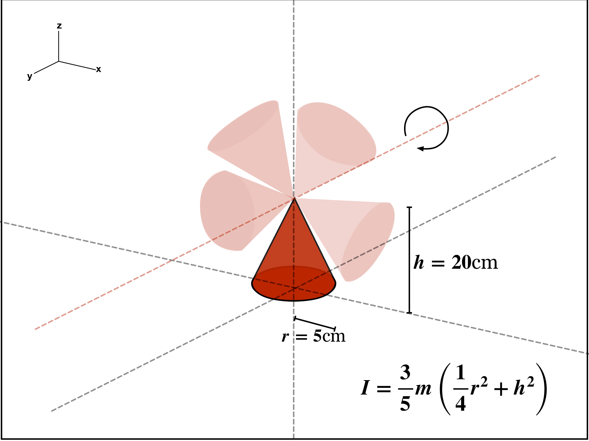
This diagram shows the cone rotating about a transverse axis through its tip. The displayed formula is I_tip. To use the parallel-axis theorem with the rocket axis, first subtract m(3h/4)² to obtain the transverse center-of-mass inertia.
Read every step and figure
Step 1
This diagram shows the cone rotating about a transverse axis through its tip. The displayed formula is I_tip. To use the parallel-axis theorem with the rocket axis, first subtract m(3h/4)² to obtain the transverse center-of-mass inertia.
Step 2
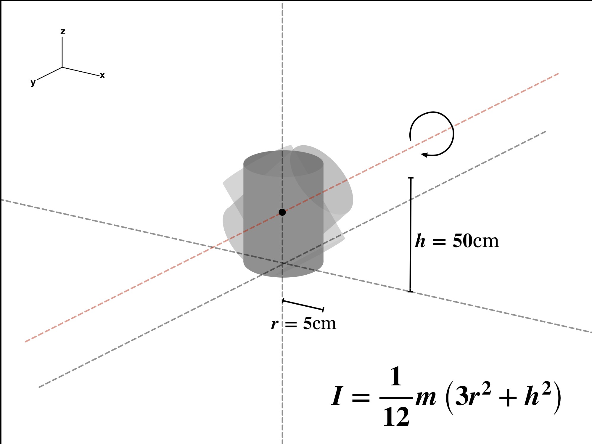
This is the body of the rocket. The MOI for this part goes through the center of the body as shown by the red axis in the image. This is why we chose the second equation from the table.
Step 3
With m = 0.500 kg, r = 0.050 m and h = 0.200 m, I_nose,CM = 0.0009375 kg·m². The tip is 0.400 m from the rocket axis, so the cone centroid is 0.400 − 0.150 = 0.250 m from it.
The rocket body can be thought of as a solid cylinder, so this means:
I_body,CM = (1/12)(1.50 kg)[3(0.050 m)² + (0.500 m)²] = 0.0321875 kg·m².
I_body,CM = 0.0321875 kg·m².
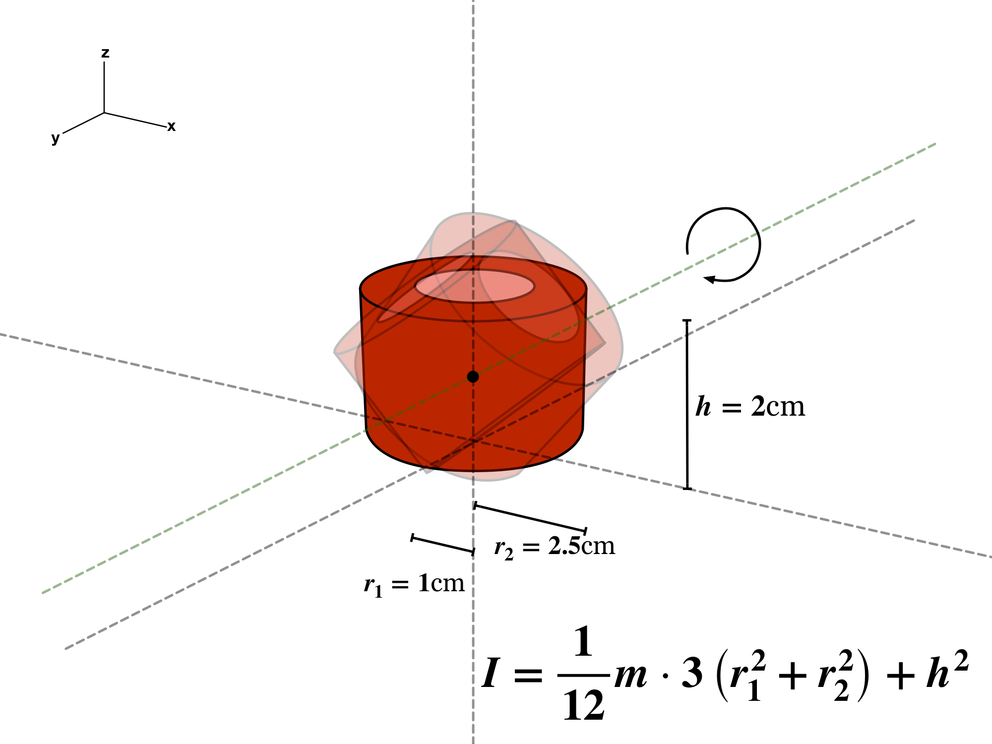
The exhaust tube can be thought of as a partial cylinder since it has an inner and outer radius:
I_exhaust,CM = (m/12)[3(r_i² + r_o²) + h²], with m = 0.025 kg, r_i = 0.010 m, r_o = 0.025 m and h = 0.020 m.
I_exhaust,CM = 5.364583 × 10⁻⁶ kg·m².
Step 3. Determine the for each component
We will need to invoke the parallel axis theorem since these shapes are all rotating at a distance, away from the central axis:
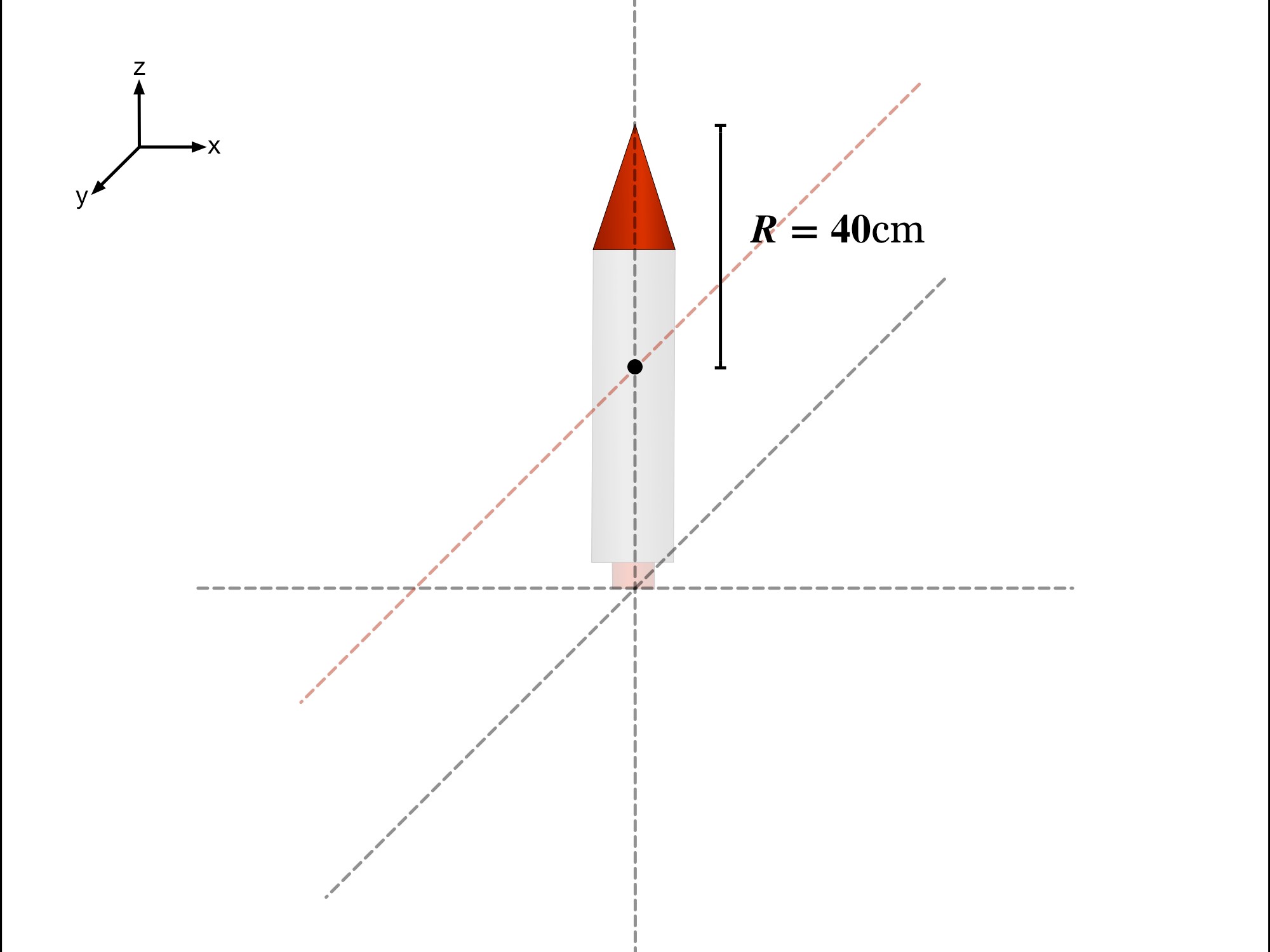
The tip is 40 cm from the rocket’s red rotation axis. A uniform solid cone’s center of mass is 15 cm behind the tip, so the centroid-to-rocket-axis separation is 25 cm. Use R = 25 cm with I_CM.
Read every step and figure
Step 1
The tip is 40 cm from the rocket’s red rotation axis. A uniform solid cone’s center of mass is 15 cm behind the tip, so the centroid-to-rocket-axis separation is 25 cm. Use R = 25 cm with I_CM.
Step 2
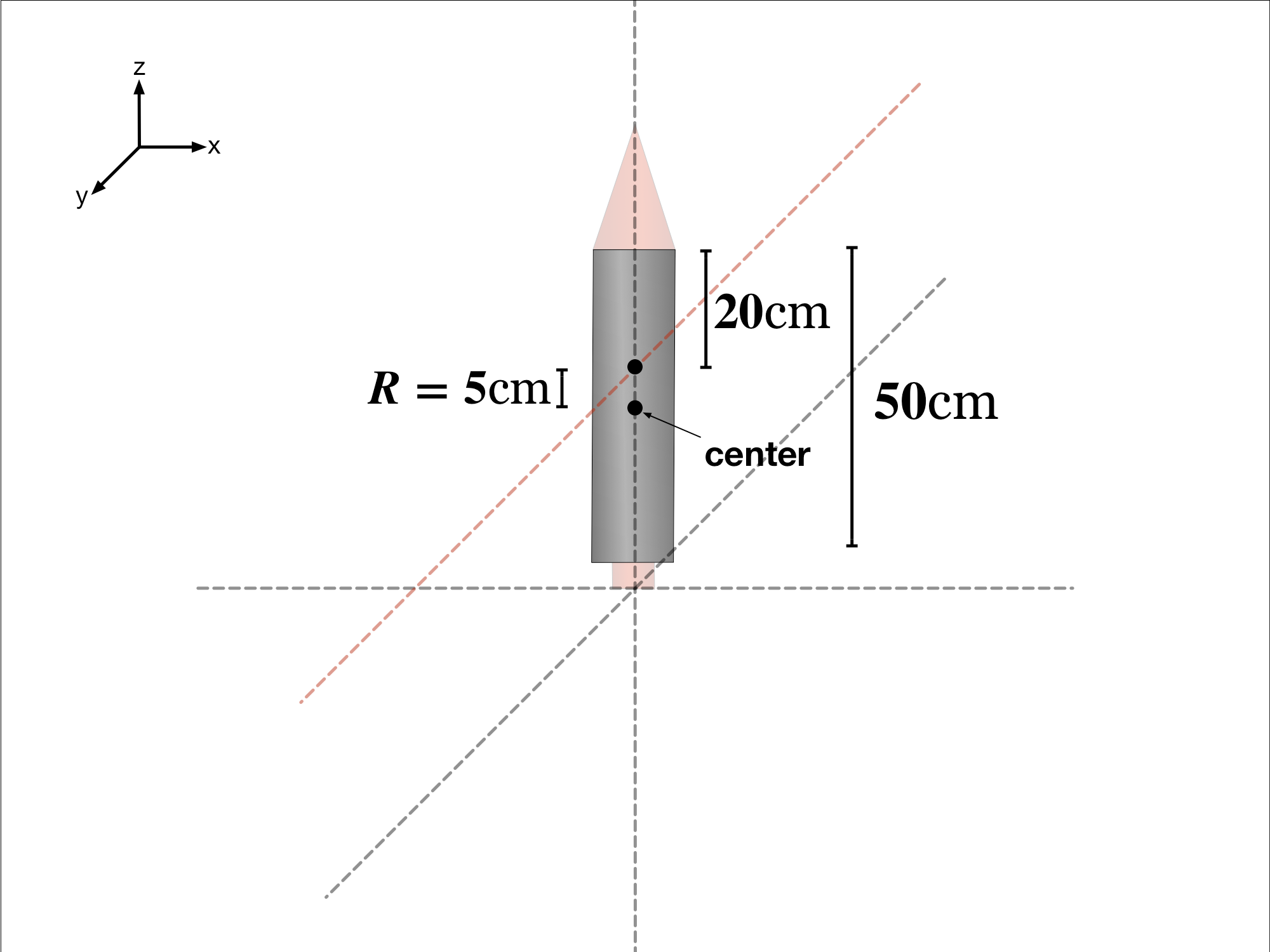
The body’s center is 25cm since it is 50cm long. Knowing that the axis of rotation is 20cm away from the top, R must then be 5cm
Step 3
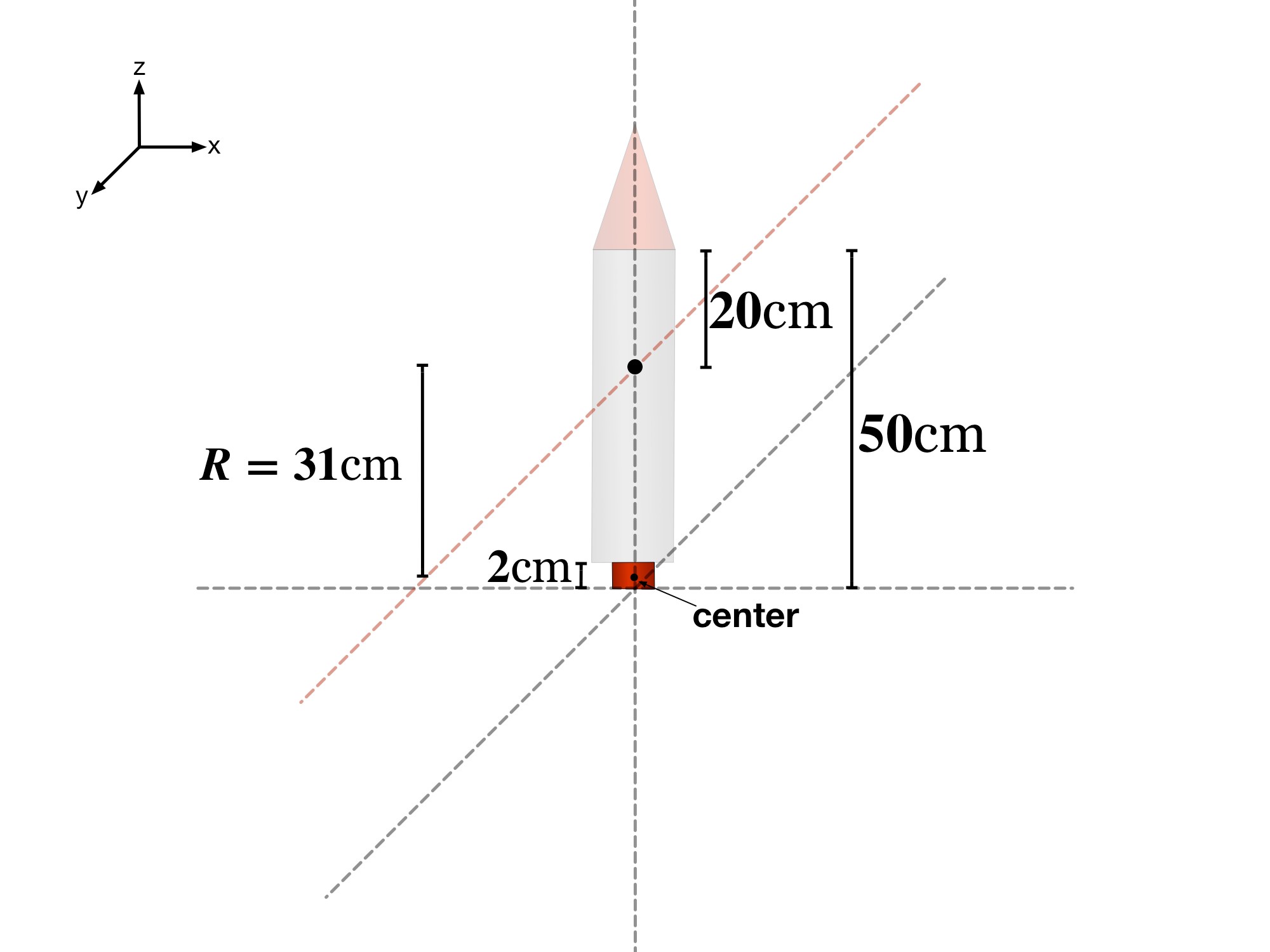
I_nose = 0.0009375 + 0.500(0.250)² = 0.0321875 kg·m². I_body = 0.0321875 + 1.50(0.050)² = 0.0359375 kg·m². I_exhaust = 5.364583 × 10⁻⁶ + 0.025(0.310)² = 0.0024078646 kg·m².
Step 4. Add up all the components
The total moment of inertia is simply the sum of all the components. This means that can be found by:
I_rocket = 0.0321875 + 0.0359375 + 0.0024078646 kg·m².


Reviewed physics notes (24)
These corrections keep the original lesson’s purpose while fixing errors in the source edition.
- The governing rotational quantity is torque, not force alone. — Reference 1
- Equal forces at different lever arms do not imply equal rotations. — Reference 1
- Distance from an axis is required, not an arbitrary center-point distance. — Reference 1
- The displayed fraction in the final rod result is malformed. — Reference 1
- The parallel-axis theorem does not require an additional independent spin about the object’s center. — Reference 1
- Avoid claiming that a freely orbiting sphere necessarily spins about its own center. — Reference 1
- Retain the correctly rounded finite-cylinder end-axis result. — Reference 1
- The selected 0.030 kg·m² answer uses the shell model; a solid sphere would give 0.018. — Reference 1
- The source treated the cone’s apex-axis inertia as a centroid-axis inertia. — Reference 1
- Provide both reference axes rather than discard the apex-axis illustration. — Reference 1
- The parallel-axis displacement must be measured from the center of mass. — Reference 1
- Recompute with the source dimensions without intermediate arithmetic errors. — Reference 1
- The source 0.0316 omits/misrounds part of the radius term. — Reference 1
- The source converts 1 cm and 2 cm incorrectly and prints 0.025 g instead of 0.025 kg. — Reference 1
- Correct the exhaust-unit arithmetic. — Reference 1
- Shift each component from its own CM to the same rocket rotation axis. — Reference 1
- Use the three corrected component inertias. — Reference 1
- The source total 0.130 kg·m² double-counts the cone’s displacement and has unit errors. — Reference 1
- Retain the visual axis lesson while identifying which reference axis its formula uses. — Reference 1
- A 40 cm tip displacement cannot be used with an apex-axis inertia in I_CM + mR². — Reference 1
- The source diagram visually omits brackets around the height term; the companion text now gives the unambiguous formula. — Reference 1
- Correct disk/hoop transverse-axis coefficients and mislabeled axes. — Reference 1
- For the depicted solid cylinder about a transverse end axis, I = mL²/3 + mr²/4 ≈ 1.67 kg·m². — Reference 1
- The source 0.417 kg·m² is the thin-rod centroid value, not the depicted end-axis inertia. — Reference 1
Glossary and deeper reading · 7 refreshers
These editorial refreshers supplement the reading. Definitions and examples are added guidance; original source wording and recorded answers remain in their original context.
-
Acceleration
Acceleration is the vector rate of change of velocity with time. It can change an object’s speed, direction, or both, and it is measured in meters per second squared. For example, a satellite moving at constant speed in a circular orbit accelerates toward the center.
-
Torque
Torque describes a force’s turning effect about a chosen axis or point. Its magnitude is force times the perpendicular lever arm, and its direction or sign describes the rotation tendency. For example, pushing near the handle of a door produces more torque than the same perpendicular push near the hinge.
-
Force
A force describes an interaction that can change an object’s momentum. It is a vector measured in newtons, so both size and direction matter when forces are added. For example, a rope can pull a cart while the floor exerts friction in another direction.
-
Angular acceleration
Angular acceleration is the rate of change of angular velocity. For a fixed axis its sign follows the chosen positive rotation direction, and its units are radians per second squared. For example, a fan speeding up has angular acceleration, whereas one turning steadily does not.
-
Inertia
Inertia is an object’s resistance to a change in its velocity. Mass measures translational inertia, whereas rotational inertia also depends on how mass is distributed relative to an axis. For example, a loaded cart accelerates less than an empty cart under the same net force.
-
Parallel-axis theorem
The parallel-axis theorem relates rotational inertia about a center-of-mass axis to inertia about a parallel displaced axis. The displaced-axis value is the center-of-mass value plus total mass times the squared separation of the axes. For example, a uniform rod has greater rotational inertia about one end than about a parallel axis through its middle.
-
Center of mass
The center of mass is the position obtained by weighting each part’s position by its mass. Its motion represents the translational motion of the whole system under the net external force. For example, adding a heavy object to one end of a light bar shifts the center of mass toward that end.