AP Unit 12 Solutions
Compare your physical setup and reasoning with these worked solutions. A numerical answer is one check; the assumptions, signs, units and representations explain what it means.
Problem 1
Two identical bar magnets lie on a table, both labeled N at the left and S at the right. A student proposes cutting one into two isolated poles.
Part a
Draw or describe a full field loop for one magnet and show a compass direction at two points on its principal axis, immediately outside its left and right ends.
Outside the field leaves N and enters S; through the magnet it returns S to N. At the point just left of N, the compass north end points left, away from N. At the point just right of S, it also points left, toward S.
Why this step? A vector map gives the local compass alignment and closed paths.
Answer and check
The loop is closed. At both specified axial points the compass north end points left: away from N on the left and toward S on the right.
Part b
Explain the poles produced by cutting, the interaction of two facing N ends, and how field strength changes when the probe is moved farther from a fixed magnet.
Both pieces remain dipoles; their cut faces carry opposite polarities. Two facing N ends repel. Moving farther weakens the dipole field.
Why this step? Atomic dipoles remain together, like polarity repels, and a dipole field decreases with distance.
Answer and check
No isolated pole results; N faces repel; the field weakens with distance.
Scoring and feedback
Problem 2
A class tests three small samples in the same external field. A retains strong magnetization, B has a weak temporary parallel response, and C has a weak temporary opposite response.
Part a
Identify each behavior and explain it in terms of electron-associated dipoles and domain or dipole alignment. Give one appropriate example material for A and B.
A is ferromagnetic, such as iron: domains can align and retain magnetization. B is paramagnetic, such as aluminum: dipoles align weakly and do not retain alignment. C shows net diamagnetism: electronic response produces an opposite contribution.
Why this step? Composition and collective arrangement determine the bulk response, not isolated poles.
All three have a diamagnetic contribution even if it is masked in A and B; permanent and induced magnetism are whole-system consequences of dipole alignment.
Why this step? A component common to all matter can be outweighed by another component.
Answer and check
A: ferromagnetic; B: paramagnetic; C: diamagnetic net response. Electron motion and spin underlie atomic dipoles.
Part b
Explain what permeability measures. Why should a measurement on A specify temperature, field strength, and orientation? Contrast it with μ₀.
Permeability describes magnetization response to an applied field. Domain configurations, temperature, orientation, and saturation at high field can change that response.
Why this step? Matter’s response depends on its composition, arrangement, and measurement conditions.
μ₀ is the free-space constant appearing in AP field relationships; it is not the condition-dependent permeability of sample A.
Why this step? Distinguish the vacuum model from a material response.
Answer and check
A material value requires specified conditions; μ₀ is constant in free space.
Part c
A compass is taken far from these samples and current sources. State an approximate model for the field that still aligns it and explain the polarity near geographic north.
Earth is approximately a magnetic dipole. Its region near geographic north acts approximately as magnetic south, aligning the north-seeking end toward it.
Why this step? Compass alignment follows local B; geographic north is not the magnetic north polarity of a bar magnet.
Answer and check
An approximate Earth dipole remains; the region near geographic north has approximately south magnetic polarity.
Scoring and feedback
Problem 3
A small positive charged object travels right at constant speed. Consider observation points U directly above it, D directly below it, and F directly ahead, all at the same distance.
Part a
Represent the magnetic field direction at U, D, and F. Explain which points have the largest field magnitude for this speed and distance.
For positive charge, v × r is out of the page at U, into the page at D, and zero at F. U and D are perpendicular to v, so the source-field magnitude is greatest there.
Why this step? Use the position vector from the source to each point, not a field vector from elsewhere.
Answer and check
U: ⊙; D: ⊗; F: zero. U and D have equal maxima.
Part b
At U, predict the change if speed increases while distance stays fixed; if distance increases while speed stays fixed; and if charge changes sign with the same magnitude.
Increasing speed strengthens B; increasing distance weakens B; changing charge sign reverses B.
Why this step? The source field depends on velocity, spatial separation, and charge sign.
Answer and check
Stronger; weaker; reversed into the page.
Part c
A second positive charged object is moving right through point U. Using the first object’s source field from part (a), predict the second object’s magnetic-force direction. Distinguish the source from the responding charge, and compare the magnetic force if the second object were stationary.
The first right-moving positive object creates an out-of-page magnetic field at U. For the second positive object, index along its rightward velocity and middle along that out-of-page field give a downward force.
Why this step? The source-field rule uses the first object’s v and r; the force rule uses the second object’s v and the source B.
If the second object is stationary, its magnetic force is zero. An electric force from the first charge may still act.
Why this step? Magnetic interactions require a moving responding charge, while electric interactions can act on a stationary charge.
Answer and check
The first object produces B; the second moving object feels a downward magnetic force. A stationary second object has zero magnetic force.
Scoring and feedback
Problem 4
An electron (q = −1.60 × 10⁻¹⁹ C, m = 9.11 × 10⁻³¹ kg) moves right at 1.00 × 10⁶ m/s into a 0.0200 T uniform field pointing into the page.
Part a
Derive the circular-path radius from magnetic force and centripetal force, then find the initial force and numerical radius. State what happens to speed while only B acts.
. The radius uses |q| and is positive for either charge sign.
Why this step? The perpendicular magnetic force provides the centripetal force, so equating the two and solving derives the radius rather than assuming it.
F = |q|vB = 3.20 × 10⁻¹⁵ N. The positive-charge direction is up, so the electron force is down.
Why this step? The velocity is perpendicular to B; reverse the right-hand-rule direction for negative q.
r = mv/(|q|B) = 2.85 × 10⁻⁴ m. Speed stays constant because magnetic force is perpendicular to motion.
Why this step? The nonrelativistic speed allows the centripetal-force model; B does no work.
Answer and check
3.20 × 10⁻¹⁵ N downward; r = 0.285 mm; constant speed.
Part b
Find the direction and magnitude of an electric field that makes the electron travel straight at this speed. Explain why matching magnitudes without directions is insufficient.
The magnetic force is down. The electron’s electric force must be up, so E points down. E = vB = 2.00 × 10⁴ V/m.
Why this step? Negative charge feels electric force opposite E; the two independent force vectors must cancel.
Answer and check
E = 2.00 × 10⁴ V/m downward. Equal magnitudes in the same direction would add.
Part c
If instead the velocity were parallel, antiparallel, or oblique to B, compare force magnitudes qualitatively with the original case.
Parallel and antiparallel give zero force. An oblique velocity gives a nonzero force smaller than the original perpendicular maximum at the same speed.
Why this step? Only the perpendicular velocity component contributes; quantitative oblique-angle force analysis is outside the AP boundary here.
Answer and check
Force is zero for 0° and 180°. For either an acute or obtuse oblique angle between 0° and 180°, excluding 90°, it is nonzero and smaller than the perpendicular maximum |q|vB. This comparison is qualitative.
Scoring and feedback
Problem 5
A long straight wire runs vertically in the page and carries 5.00 A upward. A point P is 0.0400 m to its right.
Part a
Find the field magnitude and direction at P. Describe its circular geometry and components.
B = μ₀I/(2πr) = 2.50 × 10⁻⁵ T. Upward current gives into-page B on the right. The field is tangent to a concentric circle, with neither radial nor axial component.
Why this step? The long-wire model uses the perpendicular distance to the wire axis.
Answer and check
25.0 μT into the page; purely tangential field.
Part b
At fixed I = 5.00 A, create quantitative graphs of B against r and B against 1/r using points at r = 0.0200, 0.0400, and 0.0800 m. Label axes with units, use suitable scales, and plot all three points. Give the straight-line slope and predict B at twice P’s distance when the current triples.
B versus r is an inverse curve. B versus 1/r is straight through the origin, with slope μ₀I/(2π) = 1.00 × 10⁻⁶ T·m.
Points for the two field graphs r (m) 1/r (m⁻¹) B (μT) 0.0200 50.0 50.0 0.0400 25.0 25.0 0.0800 12.5 12.5 Use a horizontal r axis from 0 to 0.0800 m and vertical B axis from 0 to at least 50.0 μT for the inverse curve. For the linear graph use horizontal 1/r from 0 to 50.0 m⁻¹ and the same B scale; the three points lie on B = (1.00 μT·m)(1/r). The slope is 1.00 μT·m = 1.00 × 10⁻⁶ T·m.
Why this step? Linearization exposes the proportionality and gives slope units.
New B = (3/2)(25.0 μT) = 37.5 μT.
Why this step? B is proportional to I and inversely proportional to r.
Answer and check
Slope 1.00 × 10⁻⁶ T·m; new field 37.5 μT.
Scoring and feedback
Problem 6
A rectangular loop carries a counterclockwise current as viewed in the page. It is first isolated, then placed in a uniform external field pointing rightward in the page.
Part a
State the direction of the loop’s own field at its center. Explain why this should not be used as the external field in calculating the loop’s force.
Curling right fingers with counterclockwise current gives out-of-page B at the center. The force question concerns the separately specified external rightward field.
Why this step? A current creates a field; the source’s own field and the applied field have different roles.
Answer and check
Own central field out of the page, along the loop axis.
Part b
The loop has vertical side length 0.0600 m, horizontal side length 0.100 m, I = 2.00 A, and external B = 0.300 T rightward. Find the force on each vertical side and the net force on the whole loop. Can it turn?
Counterclockwise current is upward on the right side and downward on the left. Each vertical force has magnitude IℓB = 0.0360 N: right side into the page and left side out of the page.
Why this step? Use conventional current crossed with the external B.
Horizontal sides are parallel or antiparallel to B and feel zero force. The whole loop has zero net force, but the opposite vertical forces form a torque and can turn it.
Why this step? Net translational force and a turning pair are different.
Answer and check
Each vertical side: 0.0360 N in opposite page directions. Net force zero; nonzero turning tendency.
Part c
Two long parallel wires carry equal currents out of the page. Explain the net field at their midpoint; then reverse one current while keeping its magnitude unchanged.
Initially their tangent fields at the midpoint are equal and opposite, so net B is zero. Reversing one current reverses its field, so the midpoint fields add.
Why this step? Magnetic fields superpose as vectors, not unsigned magnitudes.
Answer and check
Zero initially; twice either individual field magnitude after reversal.
Scoring and feedback
Problem 7
A single loop of area 0.0400 m² has its chosen normal out of the page. The field is normal to it: +0.20 T at t = 0, +0.50 T at t = 0.30 s, constant until t = 0.60 s, then −0.10 T at t = 0.90 s. Each transition is linear.
Part a
Calculate signed flux at each listed time. Explain the negative final value and state how the normal is chosen for an open loop versus a closed surface.
Flux = BA because the signed field is along the chosen normal. Values are +0.00800, +0.0200, +0.0200, and −0.00400 Wb.
Why this step? The sign indicates alignment or opposition to the normal.
For an open loop either normal may be chosen consistently. A closed surface uses an outward normal at each patch.
Why this step? Orientation belongs to the definition of the area vector.
Answer and check
Final flux is negative because B opposes the chosen out-of-page normal.
Part b
Create a quantitative emf-versus-time graph with labeled axes, units, a suitable vertical scale, and the three interval levels from t = 0 to 0.90 s. State current circulation in each interval if R = 4.00 Ω, and define positive circulation.
Positive circulation is counterclockwise for the out-of-page normal. Emfs from negative flux slopes are −0.0400 V, 0, and +0.0800 V.
Why this step? Faraday’s minus sign uses a circulation paired with the selected normal.
Current is 0.0100 A clockwise, zero, and 0.0200 A counterclockwise. In the last interval the induced field is out of the page throughout, resisting the falling signed flux even after the external B changes sign.
Why this step? Ohm’s law gives magnitude; Lenz’s law opposes the change rather than the original field.
Answer and check
Piecewise constant emf: −0.0400, 0, +0.0800 V.
| Interval (s) | ΔΦ (Wb) | Emf (V) | Current |
|---|---|---|---|
| 0 to 0.30 | +0.0120 | −0.0400 | 0.0100 A clockwise |
| 0.30 to 0.60 | 0 | 0 | 0 |
| 0.60 to 0.90 | −0.0240 | +0.0800 | 0.0200 A counterclockwise |
Scoring and feedback
Problem 8
A conducting rod of length 0.150 m moves right at 2.00 m/s on rails joined at the left. B = 0.600 T points into the page and total resistance is 3.00 Ω.
Part a
Derive the emf from the area change, then calculate emf and current. Give the current direction.
Area changes at ΔA/Δt = ℓv. With B normal to the loop, |ℰ| = BΔA/Δt = Bℓv = 0.180 V.
Why this step? Faraday converts geometric area growth into flux change.
I = 0.180/3.00 = 0.0600 A, up the rod and counterclockwise.
Why this step? Its field points out of the page to resist increasing into-page flux.
Answer and check
0.180 V and 0.0600 A counterclockwise.
Part b
Find the external force and power needed for constant speed; independently check the power using electrical heating.
The magnetic force on the rod is leftward with magnitude IℓB = 0.00540 N, so the external force is 0.00540 N rightward.
Why this step? Constant speed requires zero net horizontal force.
P = Fv = 0.0108 W and I²R = 0.0108 W.
Why this step? External mechanical work supplies resistive heating.
Answer and check
F_ext = 0.00540 N rightward; P_ext = 0.0108 W.
Scoring and feedback
Problem 9
A low-current Hall sensor measures a straight wire’s field. Positive carriers drift horizontally right at 12.0 m/s. The sensor’s transverse width is w = 0.0200 m, measured vertically in the page, perpendicular to that drift. At the sensor the wire field is into the page.
Part a
Predict which sensor edge has higher electric potential. At equilibrium derive the transverse voltage magnitude in terms of v, B, and width w.
Positive carriers feel upward magnetic force, so the upper edge accumulates positive charge and is at higher potential. Balancing transverse forces gives E = vB, and |ΔV| = Ew = vBw.
Why this step? The Hall voltage arises from charge separation until electric and magnetic forces cancel.
Answer and check
Upper edge higher; |ΔV| = vBw.
Part b
The Hall voltage is 6.00 μV when the sensor is 0.0400 m from a long wire. Estimate wire current. Predict voltage at twice the distance if sensor orientation and carrier speed remain fixed.
B = |ΔV|/(vw) = 6.00 × 10⁻⁶/(12.0 × 0.0200) = 2.50 × 10⁻⁵ T. I = 2πrB/μ₀ = 5.00 A.
Why this step? Use the Hall force balance, then the independent long-wire field model.
Twice r halves B, hence halves the Hall voltage to 3.00 μV.
Why this step? All sensor factors are held fixed, so voltage follows B.
Answer and check
5.00 A; 3.00 μV at twice the distance.
Scoring and feedback
Problem 10
Design a hands-on test of B ∝ I/r using a long straight insulated wire, a low-voltage current-limited supply, ammeter, magnetic-field probe, and ruler. Earth’s field and probe offset are not negligible.
Part a
Give a procedure that isolates the wire field, controls geometry, and tests both current dependence and distance dependence.
Fix probe orientation tangent to the expected field, measure distance from wire axis, keep return lead far away, and work near the middle of a long straight section. Measure the same position with +I and −I and use [B(+I)−B(−I)]/2 to remove the stable background.
Why this step? Reversal changes the wire contribution while the approximately static Earth field and offset remain.
At fixed r take several current settings; graph isolated B versus I. At fixed I take several r settings; graph B versus 1/r. Repeat measurements and include zero-current checks.
Why this step? Controlled variations and linear graphs test the two proportionalities separately.
Answer and check
A valid test varies one independent variable at a time and removes the stable background using current reversal.
Part b
At I = 2.00 A, r values of 0.0200, 0.0400, and 0.0800 m give isolated fields 20.4, 9.8, and 5.1 μT. Compute Br for each. Identify a major uncertainty and a justified conclusion.
Br values are 4.08 × 10⁻⁷, 3.92 × 10⁻⁷, and 4.08 × 10⁻⁷ T·m. The prediction μ₀I/(2π) is 4.00 × 10⁻⁷ T·m.
Why this step? An inverse relationship makes the product approximately constant.
Probe position uncertainty is especially consequential at the smallest r; probe angular alignment and nearby current paths also matter. The data support the long-wire inverse-distance model within a few percent, provided uncertainties are comparable.
Why this step? Agreement should be assessed against uncertainty, not declared exact from rounded values.
Answer and check
The roughly constant Br agrees with 4.00 × 10⁻⁷ T·m to about 2%; report measurement uncertainty before claiming a precise confirmation.
Scoring and feedback
Problem 11
A vertical conducting rod, perpendicular to two horizontal rails joined at the left, slides right and increases their enclosed area. Uniform B = 0.500 T points into the page, normal to the rail-loop plane; rod length ℓ = 0.100 m, motion, and B are mutually perpendicular. First an effectively open circuit with a high-resistance voltmeter measures emf; then a resistor closes the circuit with total R = 2.00 Ω and the external pulling force is measured. Compare steady test speeds v = 1.00 m/s and 2.00 m/s. For the ideal table neglect friction, rail/rod resistance beyond the stated total, and self-induction; part (b) considers possible experimental friction.
Part a
Construct a numerical table of emf, closed-circuit current, resisting magnetic-force magnitude, and mechanical power at both speeds. Derive the symbolic speed dependence of power from the rod emf and wire-force relationships, then explain why power does not scale linearly with speed.
Ideal perpendicular sliding-rod results, closed circuit v (m/s) |ℰ| (V) I (A) F_resist (N) P_ext (W) 1.00 0.0500 0.0250 0.00125 0.00125 2.00 0.100 0.0500 0.00250 0.00500 Current is counterclockwise, up the rod. The magnetic force on the rod points left; the external force at steady speed points right.
Why this step? Apply Bℓv, Ohm’s law, IℓB, and Fv sequentially.
. Then . Thus doubling v quadruples power, although emf, current, and force each double.
Why this step? There are two factors of v in the power, unlike the emf.
Answer and check
| v (m/s) | |ℰ| (V) | I (A) | F_resist (N) | P_ext (W) |
|---|---|---|---|---|
| 1.00 | 0.0500 | 0.0250 | 0.00125 | 0.00125 |
| 2.00 | 0.100 | 0.0500 | 0.00250 | 0.00500 |
The high-speed power is four times the low-speed power, consistent with P = I²R. The force resists motion, and external work supplies the heating.
Part b
State what would change if the circuit were opened, and propose a measurement that distinguishes friction from induction-related resistance.
An open rod still has a motional potential difference but essentially no steady circuit current, so the induced IℓB drag and resistive heating vanish in the ideal model.
Why this step? An emf is distinct from a sustained closed-circuit current.
At the same constant speeds compare pulling force with the circuit open and closed; subtract the open-circuit baseline. Hold mechanical alignment fixed and reverse B as a check: induced drag still opposes motion.
Why this step? A controlled baseline can separate mechanical friction from the electrical load.
Answer and check
Opening removes load current and its magnetic drag; a closed-minus-open force comparison isolates the induction contribution.
Scoring and feedback
Explain and apply: worked solutions
Compare the physical setup and the reasoning, as well as the final answer. Give credit for equivalent correct reasoning, using the rubric to find your next step.
From circular charge motion to a magnetic material
A classical charge +4.00 nC circulates counterclockwise once every 2.00 μs as viewed along the loop axis. Separately, an iron sample and an aluminum sample are placed in the same external magnetic field and then removed. These are distinct classical-loop and material experiments.
Part a
Calculate the equivalent conventional current. Explain why the circular charge motion produces a magnetic dipole and determine its central field direction and the polarity of the face you view. Then predict both directions if the circulating charge is negative with the same magnitude and motion.
The positive charge gives 2.00 mA counterclockwise, central B out of the page, and a north viewing face. For negative charge with the same counterclockwise motion, conventional current is clockwise, central B points into the page, and the viewing face is south.
- I = Q/T = (4.00 × 10⁻⁹)/(2.00 × 10⁻⁶) = 2.00 × 10⁻³ A.
- Circular charge transport is a circulating current; a loop has an axial dipole field with both north and south polarity.
- Curl with conventional current, reversing the current sense for negative moving charge.
Scoring criteria
- Credit 2.00 mA with correct conversion and units.
- Credit circulating charge → current loop → magnetic dipole explanation.
- Credit both axial directions and associated viewing-face polarities, using conventional current.
Part b
Explain how electron motion can contribute magnetic dipoles in matter. Assess the statement “electron spin means a tiny charged sphere physically rotating”; distinguish the classical orbital/circulating-charge analogy from intrinsic spin.
Electron orbital motion can contribute atomic magnetic dipoles through its moving-charge character. Intrinsic electron spin has an associated magnetic moment but is a quantum property; it is not ordinary rotation of a charged sphere.
- Identify orbital/moving-charge magnetic contributions.
- Explain the current-loop analogy for circular motion without presenting a classical orbit as the full quantum atom.
- State separately that intrinsic spin is not a classical spinning-ball mechanism.
Scoring criteria
- Credit a circular/orbital moving-charge contribution.
- Credit intrinsic spin’s magnetic contribution and explicitly reject literal classical sphere rotation.
Part c
Use the configuration of dipoles and domains to explain why the iron may retain magnetization whereas aluminum has only weak temporary magnetization. State what happens to the paramagnetic alignment after field removal, and explain whether the diamagnetic contribution is absent from iron.
Iron is ferromagnetic: the external field favors similarly oriented domains, and substantial collective alignment may persist after removal. Aluminum is paramagnetic: its weak preferred dipole alignment does not persist once the field is removed. Both have a usually weak opposite diamagnetic contribution; iron’s stronger ferromagnetism can mask it.
- Use the material’s composition to distinguish collective ferromagnetic domains from weak paramagnetic response.
- Compare configurations with the field present and after its removal.
- Distinguish a universal diamagnetic contribution from the dominant net observed behavior.
Scoring criteria
- Credit retained domain alignment as the cause of possible permanent iron magnetization.
- Credit weak aluminum alignment and its loss on field removal.
- Credit all-material diamagnetism and masking by a stronger contribution.
Return to the unit problem →Try this problem in its lesson →
Connect a field map to its inverse-distance graphs
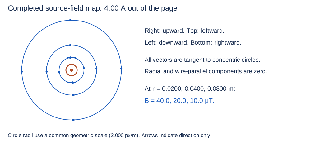
A long wire in air carries 4.00 A out of the page. Measure at P to the right of its axis at r = 0.0200, 0.0400, and 0.0800 m, outside the wire and far from its ends. Use μ₀ = 4π × 10⁻⁷ T·m/A.
Part a
Draw an arrowed field map around the wire, showing tangent directions at its right, top, left, and bottom. Explain whether B has radial or wire-parallel components, and calculate B at the three specified radii.
The map consists of counterclockwise concentric circles: right upward, top leftward, left downward, bottom rightward. Radial and axial components are zero. B values are 40.0, 20.0, and 10.0 μT.
- Curl right fingers about an out-of-page right thumb.
- Use the shortest perpendicular radius from the wire axis.
- B = (8.00 × 10⁻⁷ T·m)/r.
Scoring criteria
- Credit four correct tangential directions and concentric geometry.
- Credit no radial/axial component.
- Credit all three numerical fields with units.
Part b
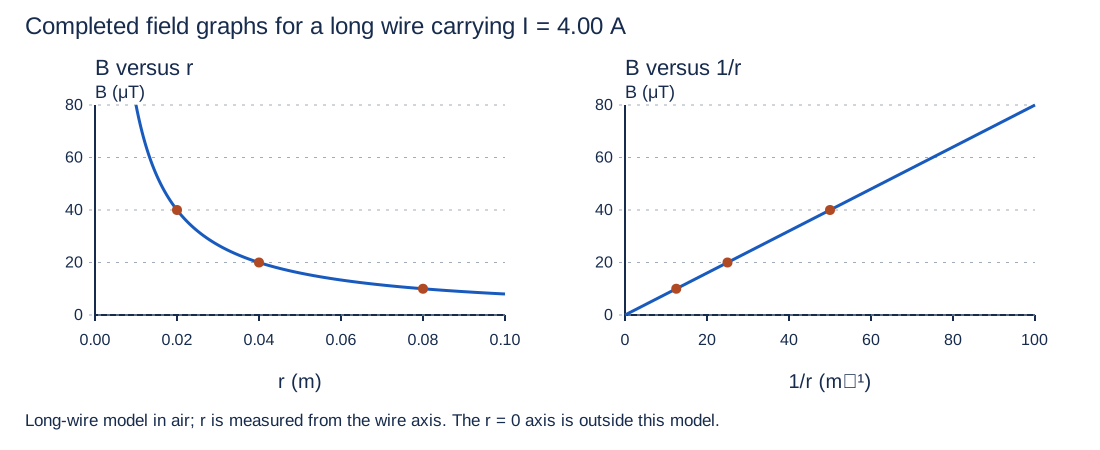
Create B-versus-r and B-versus-1/r graphs using all three points. Supply numerical axes, scales, and units; distinguish the inverse curve from a straight fit. Determine the straight-line slope with units. Explain why its origin does not describe r = 0. Predict B at r = 0.0800 m if the current becomes 12.0 A.
The inverse plot contains (0.0200 m,40.0 μT), (0.0400 m,20.0 μT), (0.0800 m,10.0 μT). The straight plot contains (50.0 m⁻¹,40.0 μT), (25.0 m⁻¹,20.0 μT), (12.5 m⁻¹,10.0 μT), with slope 0.800 μT·m = 8.00 × 10⁻⁷ T·m. Its origin means 1/r = 0, the far-distance limit. Tripling current makes the last field 30.0 μT.
- Calculate each reciprocal radius.
- Place both sets of points on labeled axes; the same B scale is permissible for both.
- Fit B = (0.800 μT·m)(1/r); compute slope as ΔB/Δ(1/r).
- Use proportionality to I at fixed r, not a change in the graph’s radius.
Scoring criteria
- Credit both actual plots with all numerical points, scales and units.
- Credit curved inverse dependence versus straight line and slope units.
- Credit far-distance meaning of the linearized origin and 30.0 μT scaling.
Inspect diagram labels
The diagram keeps its full size here. Focus the view and use the arrow keys, or scroll across it, to inspect every label.
Inspect diagram labels
The diagram keeps its full size here. Focus the view and use the arrow keys, or scroll across it, to inspect every label.
Return to the unit problem →Try this problem in its lesson →