Images Formed by Mirrors
Construct mirror images while keeping real paths, extensions, and signed focal lengths distinct.
AP Physics 2 Topic 13.2 · College Board CED printed p. 96, 97 / PDF p. 103, 104 · See this topic in the course outline
A mirror can send rays together or make them look as if they came from behind it. Keep actual paths and backward extensions separate; then the image-distance sign has a physical meaning.
Before you start
- Reflection law
- Signed reciprocals
- Ratio and similarity
Where mirrors send parallel rays
A concave spherical mirror is converging: rays parallel to its principal axis reflect toward a focal point in front of the mirror. A convex spherical mirror is diverging: reflected parallel rays spread out, and their backward extensions meet at a focal point behind the mirror. A plane mirror keeps parallel rays parallel, corresponding to a focal point at infinite distance.
For a spherical mirror and rays close to the principal axis, , where R is the ordinary nonnegative radius of curvature. The optical focal length is positive for a concave mirror and negative for a convex mirror. The principal axis passes through the vertex (where the axis meets the mirror) and the center of curvature. The focal point is approximately halfway between those points. This is a paraxial approximation: far-off-axis rays can fail to meet at exactly one focus. AP mirror scope here is plane, concave spherical, and convex spherical mirrors.
Locate real and virtual mirror images
Start from a single object point and trace at least two reflected rays. A real image forms where the actual reflected rays intersect; it can be received on a screen placed there. A virtual image forms where backward extensions of diverging reflected rays intersect. Light does not travel along those dashed extensions, so a screen at that location cannot receive the image, although an observer can see it by receiving the rays.
Use this real-is-positive convention: a real object in front has ; a real mirror image in front has ; a virtual image behind has . Concave f is positive; convex f is negative. Distances are measured from the mirror vertex. The mirror equation is . Do not attach a negative sign simply because a coordinate is drawn to the left: these are optical signs, not ordinary x coordinates.
For a plane mirror, 1/f = 0, so . Its virtual image is as far behind the mirror as the object is in front. A ruler gives equal positive distance magnitudes, while the equation uses opposite signed distances.
Construct a mirror image with the principal rays
Draw the object as an arrow perpendicular to the principal axis, mark F and the mirror vertex, and start rays from the object tip. Three useful rays are: (1) a ray parallel to the axis reflects through the concave focus, or appears to come from the convex focus; (2) a ray striking the vertex reflects with equal angles to the principal axis, which is the normal there; (3) a ray passing through the concave focus reflects parallel to the axis. For a convex mirror, aim this third ray toward the virtual focus behind it; the reflected ray is parallel.
For a virtual image, extend reflected rays backward using dashed lines. Two accurate rays determine the tip; the third is a check. In the concave construction below, the object is 30 cm in front of a mirror with f = 10 cm. The reflected rays intersect 15 cm in front and below the axis, giving an inverted image half as tall as the object.
Use magnification to read size and orientation
The signed transverse magnification is . Its magnitude gives size ratio, the form supplied in the CED. With an upright positive object height, m > 0 means upright and m < 0 means inverted. A virtual image does not necessarily mean “small”: a concave mirror with the object inside the focal length gives an upright enlarged virtual image.
| d_o (cm) | d_i (cm) | m | Image description |
|---|---|---|---|
| 30 | +15 | −0.50 | Real, inverted, reduced |
| 20 | +20 | −1.0 | Real, inverted, same size |
| 15 | +30 | −2.0 | Real, inverted, enlarged |
| 10 | No finite image | No finite value | Reflected rays parallel |
| 5 | −10 | +2.0 | Virtual, upright, enlarged |
For a convex mirror and a real object, the image is always virtual, upright, and reduced. A plane mirror gives m = +1: upright, virtual, and the same size. Use an equation, a ray sketch, and the sign of magnification as mutual checks.
Calculate and sketch a concave-mirror image
A 3.00 cm tall object is 18.0 cm in front of a concave spherical mirror with radius 24.0 cm. Find the image location, height, and type.
Choose the paraxial mirror model with ordinary radius R = 24.0 cm. Because the mirror is concave, f = +R/2 = +12.0 cm and d_o = +18.0 cm.
Why this step? Concave means converging and positive f in the stated convention.
1/d_i = 1/12.0 − 1/18.0 = 1/36.0 cm⁻¹, so d_i = +36.0 cm.
Why this step? Solve the signed equation before interpreting the image.
m = −36.0/18.0 = −2.00 and h_i = m h_o = −6.00 cm.
Why this step? The sign gives orientation and the magnitude gives size.
A parallel ray reflects through F; a vertex ray reflects with equal angles. They meet in front, below the axis, farther than the center of curvature.
Why this step? The real inverted enlarged ray construction checks both distance and height.
Answer and check
Image 36.0 cm in front, real, inverted, 6.00 cm tall.
Interpret a negative image distance
An object is 30.0 cm in front of a convex mirror with f = −15.0 cm. Locate and describe the image.
Use d_o = +30.0 cm and f = −15.0 cm. Then 1/d_i = −1/15.0 − 1/30.0 = −1/10.0 cm⁻¹.
Why this step? The negative focal length belongs to a diverging mirror.
d_i = −10.0 cm and m = −(−10.0)/30.0 = +1/3.
Why this step? Negative d_i places the image behind the mirror; positive m means upright.
Reflected rays diverge; their backward extensions meet between the vertex and virtual focal point.
Why this step? A convex-mirror ray construction agrees with a virtual reduced image.
Answer and check
10.0 cm behind the mirror; virtual, upright, one-third as tall.
Use the third ray to check the mirror image
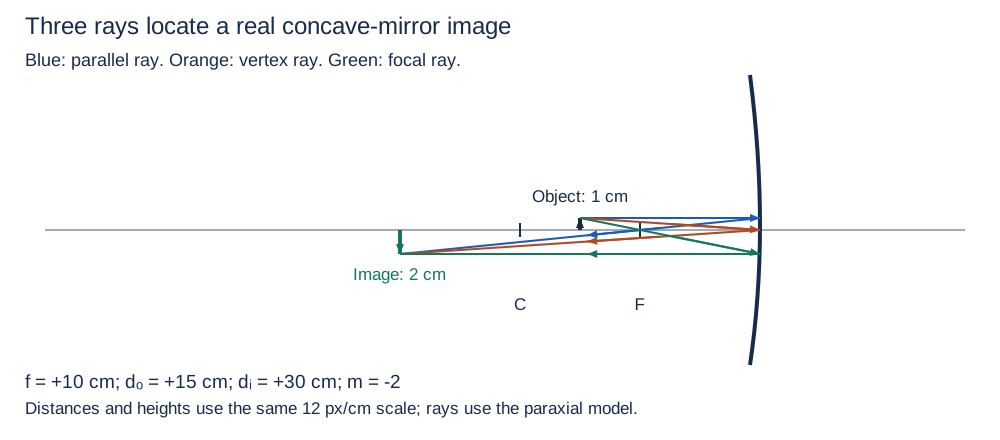
Start all three principal rays at one object tip. For a concave mirror, the parallel ray reflects through the front focus; the vertex ray reflects at equal angles to the axis; and a ray through the front focus reflects parallel to the axis. The vertex ray is not the same construction as a ray through the center of curvature. Their different routes must predict one image point in the paraxial approximation.
In the diagram, the three actual reflected rays intersect below the axis. That intersection makes the image real and inverted; its distance and height can be measured on the scaled diagram. A virtual mirror image instead requires dashed backward extensions of diverging reflected rays. Do not replace an actual intersection with dashed lines simply because an image is drawn to the left.
Inspect diagram labels
The diagram keeps its full size here. Focus the view and use the arrow keys, or scroll across it, to inspect every label.
Check the algebra with three reflected paths
A paraxial concave mirror has f = +10.0 cm. An upright 1.00 cm object is 15.0 cm in front. Use real-is-positive optical distances.
Inspect diagram labels
The diagram keeps its full size here. Focus the view and use the arrow keys, or scroll across it, to inspect every label.
- 1/dᵢ = 1/10.0 − 1/15.0 = 1/30.0 cm⁻¹, so dᵢ = +30.0 cm in front.
- m = −30.0/15.0 = −2.00; hᵢ = −2.00 cm.
- Draw a parallel→focus ray, a vertex equal-angle ray, and a focus→parallel ray. All three reflected portions meet 30.0 cm in front at height −2.00 cm.
- Actual reflected intersection means real; below-axis height means inverted; |m| = 2 means enlarged.
Answer and check
Real, inverted image 30.0 cm in front, 2.00 cm tall. The three-ray plot gives the same location, height and type as the signed equation.
Try it from memory
Write your answer and reason before opening the worked answer. Your self-assessment is a study decision; it is not an automatically graded score.
Question 1
A person stands 0.80 m in front of a plane mirror. Give signed d_i and the person-to-image separation.
Worked answer and reason
d_i = −0.80 m; separation is 1.60 m.
The virtual image lies equally far behind, so person-to-image distance adds the two magnitudes.
Question 2
Why is |f| = R incorrect for a paraxial spherical mirror when R is the ordinary nonnegative radius of curvature? State the focal-length signs for concave and convex mirrors.
Worked answer and reason
The focus is approximately halfway from the vertex to the center of curvature, so |f| ≈ R/2. The optical focal length is positive for a concave mirror and negative for a convex mirror.
A parallel-ray convergence point is different from the center of curvature.
Question 3
A concave mirror produces m = +3 for a real object. Describe the image and the object’s region.
Worked answer and reason
The image is upright, enlarged, and virtual; the object is inside the positive focal length.
With d_o positive, m positive requires d_i negative. The ray extensions meet behind the mirror.
Question 4
How does the principal ray striking the vertex reflect? Is it the same as a ray aimed at the center of curvature?
Worked answer and reason
At the vertex it reflects with equal angles to the principal axis. A center-of-curvature ray is a different useful ray that retraces its path.
The axis is normal at the vertex; do not confuse “center of the mirror” with the curvature center.
JavaScript enables saved drafts and self-assessment. You can always work on paper.
Catch the tempting mistake
- A negative image distance is an impossible answer.
- It identifies a virtual image behind the mirror in the chosen convention.
- A mirror focus is at its center of curvature.
- For near-axis rays it is approximately halfway there.
- All virtual mirror images are reduced.
- A concave mirror used inside its focal length gives an enlarged virtual image.
Put it to work
Give the physical reason as well as the calculation. The worked solutions are on a separate page.
- Problem 3 · symbolic calculation and ray construction
- Problem 4 · comparison table and virtual-ray construction
- Problem 10 · comparison table and ray translation
Explain and apply the model
Try these problems before opening the solutions. Show the physical model, your calculation or sketch, and the reason your conclusion follows.
Require the reflected rays to agree
A concave spherical mirror has nonnegative radius of curvature R = 24.0 cm. A real upright object 2.00 cm tall is 18.0 cm in front. Use the paraxial approximation and the real-is-positive convention.
(a) Determine signed f, dᵢ, m, and hᵢ. State the physical image side, real/virtual type, orientation, and size relative to the object.
(b) Construct a scaled, arrowed three-principal-ray diagram from the object tip. Mark the vertex, focus, curvature center, and image. Show the parallel ray, the vertex ray, and the focal ray; explain how the actual reflected intersection establishes image type and how its height checks part (a).
Written working workspace
Drawing is temporarily unavailable. Work on paper if needed, then record your reasoning here.
Saving written working requires JavaScript. Keep your work on paper or in your own notes; the source problem above remains available.
Worked solution and rubric →Revisit the explanation →Revisit the explanation →
Scientific calculator workspace
Keep intermediate precision and report units. This calculator supports arithmetic and elementary functions.
Scientific calculator
This calculator requires JavaScript. Use the physics formula sheets and show your working manually.
+ − * / ^ ! · pi · e · sqrt · sin, cos, tan · asin, acos, atan · atan2(y,x) · ln, log · abs · exp · hypot(x,y). Use * between factors. Keep units in your written working.
For the teacher
- State the optical sign convention on the board and reuse it for every problem.
- Ask learners to point to actual ray intersections before calling an image real.
- Limit mirrors to plane, concave spherical, and convex spherical; use near-axis rays for spherical equations.
Source objectives and scope
- 13.2.A — Describe the image formed by a mirror.
AP Physics 2 limits the study of mirrors to plane mirrors, convex spherical mirrors, and concave spherical mirrors.
Suggested skills are teaching guidance. The course applies all science practices across its objectives.
Science references for this teaching
- College Board AP Physics 2 CED, Unit 13 (supplied pinned source) — Official Unit 13 requirements, plane/spherical mirror scope, and magnitude form of magnification
- OpenStax College Physics 2e: The Ray Aspect of Light — Ray and wavefront geometry; geometric-optics approximation
- OpenStax College Physics 2e: The Law of Reflection — Normal-angle law and local diffuse/specular reflection
- OpenStax College Physics 2e: Image Formation by Mirrors — Paraxial spherical mirrors, mirror distances, magnification
- OpenStax College Physics 2e: The Law of Refraction — Refractive index, speed, and Snell angles
- OpenStax College Physics 2e: Total Internal Reflection — Index-order condition and critical-angle boundary
- OpenStax College Physics 2e: Image Formation by Lenses — Thin-lens images, sign convention, and principal rays
Glossary and deeper reading · 6 refreshers
These editorial refreshers supplement the reading. Definitions and examples are added guidance; original source wording and recorded answers remain in their original context.
-
Focal point
A focal point is where rays initially parallel to the principal axis converge or appear to diverge after reflection or refraction. The principal-axis description uses the paraxial model, in which rays remain close to the axis. For example, a converging thin lens brings parallel incoming rays to its far focal point.
-
Focal length
Focal length is the signed distance from the relevant lens or mirror reference point to its principal focal point in the chosen convention. It determines how strongly the optical element converges or diverges paraxial rays. For example, a converging lens with a shorter positive focal length bends initially parallel rays to a nearer focus.
-
Reflection
Reflection occurs when a wave returns from a boundary into the region from which it arrived. For a light ray at a surface, the reflection angle equals the incidence angle when both are measured from the local normal. For example, a smooth mirror produces an orderly image while a rough surface scatters reflected rays in many directions.
-
Real image
A real image forms where light rays physically converge after leaving an optical element. It can be projected onto a screen placed at the image location. For example, a projector’s lens forms a real image of its source on a screen.
-
Virtual image
A virtual image is located where backward extensions of outgoing rays appear to meet. The rays do not physically converge at that location, so placing a screen there does not capture that image. For example, a plane mirror produces an image that appears behind the mirror.
-
Optical magnification
Optical magnification is the ratio of image height to object height in the chosen signed convention. Its magnitude gives the size ratio, while its sign indicates upright or inverted orientation. For example, an inverted image half the object’s height has negative magnification with magnitude one half.