Double-Slit Interference and Diffraction Gratings
Distinguish fine double-slit or grating directions from a finite-slit diffraction envelope.
AP Physics 2 Topic 14.8 · College Board CED printed p. 124, 125 / PDF p. 131, 132 · See this topic in the course outline
Two slits set the fine spacing. Each slit’s finite width sets a broader envelope. Many slits sharpen the bright directions.
Before you start
- Single-slit diffraction
- Superposition
- Small-angle approximation
Fine fringes from two coherent sources
Young's double-slit pattern shows light's wave properties: a single source illuminates both slits, giving a stable phase relationship. Contributions from slits separated by d differ in path by . For initially in-phase coherent light, bright directions satisfy , and dark interference directions satisfy . Equal path length gives the central bright fringe.
At |θ| < 10°, , so adjacent bright fringes are approximately uniformly spaced by λL/d. They are uniformly spaced in sin θ exactly, not generally in screen position at large angles. Increasing d packs the fringes closer; increasing λ or L spreads them.
Finite slit width a still produces single-slit diffraction. Fine interference peaks lie under the broad envelope with zeros at a sin θ = pλ. If an interference maximum coincides with an envelope zero, that bright order is missing. A photograph needs both scales: d sets fringe spacing, a sets envelope width. A perfectly narrow slit model suppresses this envelope and is an approximation.
Grating orders and white-light dispersion
A diffraction grating contains many evenly spaced parallel openings. Neighboring openings have path difference d sin θ, so principal maxima again obey . Many coherent contributions reinforce strongly only near those directions, making narrower, more distinct peaks than two slits. If a grating has G lines per meter, d = 1/G.
An order exists only if |mλ/d| ≤ 1. For white light, m = 0 puts every wavelength at θ = 0, making a white central maximum. For the same nonzero order, longer wavelength needs a larger |sin θ|, so red appears farther from center than violet. Different orders can overlap; the grating does not guarantee a unique color at every location. Use the wavelength within the propagation medium; our numerical examples use air, approximated as vacuum.
Test whether an order can exist
A grating has 500 lines/mm. For λ = 600 nm find the first-order angle and the largest possible order.
G = 5.00 × 10⁵ lines/m; d = 1/G = 2.00 × 10⁻⁶ m.
Why this step? The equation uses slit spacing, not the number of lines in the original units.
sin θ₁ = λ/d = 0.300, so θ₁ = 17.5°.
Why this step? Use the exact angular relation because the small-angle boundary is exceeded.
|m| ≤ d/λ = 3.33; the largest integer order is 3.
Why this step? A sine cannot exceed one, so the fourth order is physically impossible.
Answer and check
θ₁ = 17.5°; maximum order m = 3 on each side.
Why a grating’s white center becomes colored orders
Each evenly spaced grating opening diffracts; the many coherent contributions superpose. In a principal direction, the path difference between neighboring openings is mλ, so all corresponding phases reinforce. Adding openings at the same spacing makes this phase agreement more selective and sharpens the principal peaks without changing d sin θ = mλ.
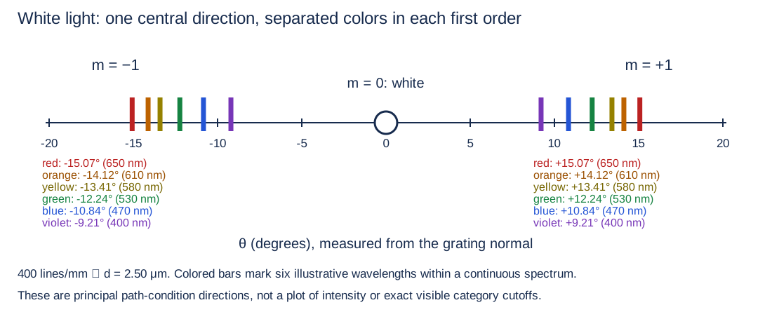
For m = 0, every wavelength has zero path difference at θ = 0, so white light’s colors overlap in a white central maximum. For a particular nonzero order, sin θ = mλ/d depends on wavelength. Red, with longer λ, appears farther from center than violet. The diagram places six sample colors on the same measured angular axis; a real white spectrum fills the intervening colors. It complements a monochromatic intensity graph, which cannot show white-light dispersion.
Inspect diagram labels
The diagram keeps its full size here. Focus the view and use the arrow keys, or scroll across it, to inspect every label.
Place red and violet on an angular scale
White light strikes a grating with 400 lines/mm normally. Compare red λ = 650 nm and violet λ = 400 nm in air. Use exact angular trigonometry.
Inspect diagram labels
The diagram keeps its full size here. Focus the view and use the arrow keys, or scroll across it, to inspect every label.
- 400 lines/mm = 4.00 × 10⁵ lines/m, so d = 1/G = 2.50 × 10⁻⁶ m.
- For m = 1, sin θred = 0.260 and sin θviolet = 0.160. Thus θred = 15.07° and θviolet = 9.21°; the negative order is symmetric.
- At m = 0, θ = 0 for both and all intervening wavelengths: their light overlaps as white.
- More coherent openings at the same d sharpen the principal peaks without moving these reference directions. A finite slit-width envelope can still weight or suppress orders.
Answer and check
The white center stays at zero; each first order spreads violet closer to center and red farther out. Red’s angle exceeds 10°, so the exact arcsine must be used.
Make the model respond
Focused Physics 2 model
Interference orders and standing waves
Predict first. Choose a model. Predict how wavelength changes bright orders or how harmonic number changes frequency.
Bright orders: d sin θₘ = mλ; exact screen y = L tan θₘ; small-angle estimate y ≈ Lmλ/d
- Exact finite screen positions
- Small-angle estimates
- Selected or reference point
On a narrow screen, scroll within a figure to read its labels. The table and explanation provide the same physics in text.
Order m = 1: θ = 14.48°, exact y = 0.5164 m; small-angle y ≈ 0.5 m.
Read the model data and comparisons
| Quantity | Value | Unit | Meaning or limit |
|---|---|---|---|
| Wavelength | 5.000 × 10^−7 | m | |
| Slit spacing | 2.000 × 10^−6 | m | |
| Screen distance | 2 | m | |
| Selected integer order | 1 | ||
| Required path difference mλ | 5.000 × 10^−7 | m | |
| Selected angle | 14.48 | ° | |
| Exact screen coordinate | 0.5164 | m | |
| Small-angle estimate | 0.5 | m | Only accurate when |mλ/d| ≪ 1 |
| Maximum allowed angular |m| | 4 | Equality gives grazing order, with no finite screen intersection | |
| Order -5 exact y | forbidden | m | |mλ/d| > 1 |
| Order -4 exact y | grazing | m | θ = -90° |
| Order -3 exact y | -2.268 | m | θ = -48.59° |
| Order -2 exact y | -1.155 | m | θ = -30° |
| Order -1 exact y | -0.5164 | m | θ = -14.48° |
| Order 0 exact y | 0 | m | θ = 0° |
| Order 1 exact y | 0.5164 | m | θ = 14.48° |
| Order 2 exact y | 1.155 | m | θ = 30° |
| Order 3 exact y | 2.268 | m | θ = 48.59° |
| Order 4 exact y | grazing | m | θ = 90° |
| Order 5 exact y | forbidden | m | |mλ/d| > 1 |
Two coherent slits produce constructive interference when the path difference is an integer wavelength. A bright-order number is an integer, not a continuous position. Convert the allowed angle to a flat-screen coordinate with tan θ. Using sin θ ≈ tan θ ≈ θ is a separate approximation and can noticeably underestimate positions at larger angles.
Assumptions and limits. Monochromatic coherent illumination, identical narrow slits, uniform center spacing, far-field interference, screen perpendicular to the central beam. The maximum-order condition uses exact trigonometry within this ideal far-field geometry. Finite slit width, missing orders from the diffraction envelope, brightness, peak width, and thin-film interference are not modeled.
Try it from memory
Write your answer and reason before opening the worked answer. Your self-assessment is a study decision; it is not an automatically graded score.
Question 1
A double-slit pattern has fine maxima under a broad envelope. Which length determines each scale?
Worked answer and reason
Separation d sets fine fringe spacing; width a of each slit sets the broad diffraction envelope.
Both slit interference and each slit’s diffraction contribute.
Question 2
Why is the central grating maximum white, but the first order separates colors?
Worked answer and reason
At m = 0 every λ has zero path difference and the same direction. At m = 1, sin θ = λ/d differs by color, with red farther out.
The grating selects equal integer path differences for each wavelength.
JavaScript enables saved drafts and self-assessment. You can always work on paper.
Catch the tempting mistake
- Every bright fringe in a real double-slit pattern has equal intensity.
- Its finite-width slits supply an envelope that modulates brightness and can remove orders entirely.
Put it to work
Give the physical reason as well as the calculation. The worked solutions are on a separate page.
- Problem 15 · mixed
- Problem 16 · mixed
- Problem 20 · experimental
- Problem 21 · mixed
Scientific calculator workspace
Keep intermediate precision and report units. This calculator supports arithmetic and elementary functions.
Scientific calculator
This calculator requires JavaScript. Use the physics formula sheets and show your working manually.
+ − * / ^ ! · pi · e · sqrt · sin, cos, tan · asin, acos, atan · atan2(y,x) · ln, log · abs · exp · hypot(x,y). Use * between factors. Keep units in your written working.
For the teacher
- Ask for both a and d on every sketch. Require sin θ ≤ 1 before accepting a grating order.
Source objectives and scope
- 14.8.A — Describe the behavior of a wave and the diffraction pattern resulting from the wave passing through multiple openings.
Suggested skills are teaching guidance. The course applies all science practices across its objectives.
Science references for this teaching
- AP Physics 2 Course and Exam Description, official Unit 14 — Official topic/LO/EK scope and boundaries; local pinned source pages 117–134, equations visually checked on 118,120,130,132,134.
- OpenStax University Physics 1, Energy and Power of a Wave — Verification of fixed-amplitude mechanical-wave frequency scaling and distinction from electromagnetic intensity.
- OpenStax University Physics 1, Interference of Waves — Linear superposition and pointwise addition model.
- OpenStax University Physics 3, Single-Slit Diffraction — Verification of aperture minima and small-angle conditions.
- OpenStax University Physics 3, Interference in Thin Films — Verification of reflection phase and normal-incidence thin-film paths.
Glossary and deeper reading · 8 refreshers
These editorial refreshers supplement the reading. Definitions and examples are added guidance; original source wording and recorded answers remain in their original context.
-
Diffraction
Diffraction is the spreading and interference of waves near openings or obstacles. The spreading is especially pronounced when the opening or obstacle size is comparable to wavelength. For example, sound spreads through a doorway much more noticeably than visible light because sound wavelengths are far larger.
-
Wave
A wave is a propagating disturbance that can transfer energy without transporting the medium as a whole. Mechanical waves require a material medium, while electromagnetic waves can propagate through vacuum. For example, a pulse travels along a rope while individual rope segments move locally around their equilibrium positions.
-
Oscillation phase
Phase specifies the position within a repeating oscillation cycle. A phase difference tells how much one oscillation leads or lags another at a chosen place and time. For example, two sinusoidal waves half a cycle out of phase can cancel when their amplitudes are equal.
-
Wave interference
Wave interference is the combination of overlapping wave disturbances. In a linear medium, the signed disturbances add at each location and time without permanently destroying the passing waves. For example, two overlapping upward rope pulses temporarily make a larger upward disturbance.
-
Diffraction grating
A diffraction grating is an array of many regularly spaced openings or scattering regions. Their coherent wave contributions produce narrow reinforced directions determined by spacing and wavelength. For example, a grating spreads white light into colored orders because different wavelengths reinforce at different angles.
-
Coherence
Coherence describes a sufficiently stable phase relationship between waves for a sustained interference pattern. It depends on the sources and on the time or distance over which their phase relationship remains predictable. For example, illuminating two slits with one suitable monochromatic source produces a stable relative phase at the slits.
-
Wavelength
Wavelength is the spatial distance between neighboring points at the same phase of a periodic wave. It connects propagation speed and frequency through speed equal to frequency times wavelength. For example, neighboring crests of a sinusoidal water wave are separated by one wavelength.
-
Wave intensity
Wave intensity is the time-averaged energy-transfer rate per area perpendicular to propagation. It is measured in watts per square meter and differs from total power because area matters. For example, spreading the same sound power over a larger area reduces the intensity there.