AP Unit 13 Solutions
Compare your physical setup and reasoning with these worked solutions. A numerical answer is one check; the assumptions, signs, units and representations explain what it means.
Problem 1
A laser beam travels through air toward a large flat mirror. Before reflection, its wavefronts are vertical parallel lines and move rightward.
Part a
Draw or describe the incident rays relative to the wavefronts. Specify arrows and explain why the ray model is suitable here.
Draw horizontal rays pointing right, perpendicular to the vertical fronts. Large optical surfaces compared with wavelength allow the geometric ray approximation.
Why this step? The ray describes propagation; the wavefront describes equal phase.
Answer and check
Horizontal rightward rays, perpendicular to fronts.
Part b
The same coherent, approximately monochromatic laser is redirected through a slit comparable to its wavelength and forms bright and dark bands on a screen. State what coherent and monochromatic mean, explain which source properties remain, and explain why rays alone fail to predict the bands.
The laser can still be coherent and approximately monochromatic, but the observed diffraction/interference needs phase and wave superposition. Straight rays alone do not predict the spreading and alternating bands.
Why this step? A coherent monochromatic beam is not exempt from wave behavior.
Answer and check
The source remains coherent and approximately monochromatic; a Unit 14 wave model is required for the bands.
Scoring and feedback
Problem 2
Three parallel rays strike a horizontal flat reflecting surface at 40.0° to the surface. The surface is then replaced by a rough sheet with tiny patches tilted differently.
Part a
Find the incidence and reflection angles for the flat surface and draw an arrowed incident/reflected pair with a normal.
θᵢ = 90.0° − 40.0° = 50.0°. θᵣ = 50.0°. Draw incoming toward the point and outgoing away on the same side of the surface.
Why this step? Convert to normal angles, then apply reflection.
Answer and check
50.0° incidence and 50.0° reflection to the normal.
Part b
Compare the reflected bundles from the smooth flat surface and rough sheet. Explain in terms of normals whether the law still holds.
Smooth flat surface: approximately parallel normals, hence a common reflected direction (specular). Rough sheet: varying normals, hence many reflected directions (diffuse). Each patch obeys equal local angles.
Why this step? The local normal controls reflection direction for each ray.
Answer and check
Specular common direction versus diffuse spread; no violation of the local reflection law.
Scoring and feedback
Problem 3
A 2.00 cm object is 30.0 cm in front of a concave spherical mirror of radius 40.0 cm. Use the real-is-positive convention.
Part a
Find f, d_i, magnification, and signed image height; classify the image.
f = R/2 = +20.0 cm. 1/d_i = 1/20.0 − 1/30.0 = 1/60.0 cm⁻¹, so d_i = +60.0 cm.
Why this step? Use the near-axis spherical approximation and positive converging f.
m = −60.0/30.0 = −2.00, h_i = −4.00 cm.
Why this step? Positive d_i makes the image real; negative magnification makes it inverted.
Answer and check
f = +20.0 cm, d_i = +60.0 cm; real, inverted, twice as tall.
Part b
Construct the three principal rays to locate the image tip. Clearly distinguish the vertex ray from a center-of-curvature ray.
From the tip draw a parallel ray reflecting through F; a ray to the vertex reflecting at equal angles to the axis; and a ray through F reflecting parallel. Their reflected portions meet below the axis 60.0 cm in front.
Why this step? A ray intersection locates the same image that the equation predicts.
The vertex ray is not generally normal to the mirror and does not generally retrace its path. A ray through the center of curvature is a separate useful normal-incidence ray.
Why this step? Avoid confusing the mirror vertex with the center of curvature.
Answer and check
Actual reflected rays meet at the real inverted image.
Scoring and feedback
Problem 4
Compare a plane mirror, a convex mirror with f = −12.0 cm, and a concave mirror with f = +12.0 cm. Each has the same upright real object 6.00 cm in front.
Part a
Calculate signed image distances and magnifications for all three mirrors. Create a comparison table including focal length, d_i, m, real/virtual type, orientation, relative size, and physical image side.
Plane: 1/f = 0, d_i = −6.00 cm and m = +1. Convex: 1/d_i = −1/12.0 − 1/6.00 = −1/4.00, so d_i = −4.00 cm and m = +2/3. Concave: 1/d_i = 1/12.0 − 1/6.00 = −1/12.0, so d_i = −12.0 cm and m = +2.00.
Why this step? The same optical equation applies with the appropriate focal-length sign.
All are virtual and upright in these cases. Plane is same size, convex reduced, concave enlarged.
Mirror comparison for a real object 6.00 cm in front Mirror f (cm) d_i (cm) m Type Orientation / size Physical location Plane Infinite −6.00 +1.00 Virtual Upright / same size 6.00 cm behind mirror Convex −12.0 −4.00 +0.667 Virtual Upright / reduced 4.00 cm behind mirror Concave +12.0 −12.0 +2.00 Virtual Upright / enlarged 12.0 cm behind mirror Why this step? Negative d_i and positive m have the same meanings across mirror types.
Answer and check
| Mirror | f (cm) | d_i (cm) | m | Type | Orientation / size | Physical location |
|---|---|---|---|---|---|---|
| Plane | Infinite | −6.00 | +1.00 | Virtual | Upright / same size | 6.00 cm behind mirror |
| Convex | −12.0 | −4.00 | +0.667 | Virtual | Upright / reduced | 4.00 cm behind mirror |
| Concave | +12.0 | −12.0 | +2.00 | Virtual | Upright / enlarged | 12.0 cm behind mirror |
All three images are virtual and upright for these object positions, but their sizes differ.
Part b
Describe the convex mirror’s parallel-ray behavior and the backward-extension construction. Could a screen behind the mirror receive its image?
A parallel incident ray reflects so its backward extension runs through the virtual focus behind the mirror. The vertex ray’s backward extension intersects it at the virtual tip.
Why this step? Actual rays diverge on the front side; extensions locate the apparent source.
A screen behind the mirror cannot receive this image because no reflected light rays actually converge there.
Why this step? Seeing a virtual image through outgoing rays differs from projecting it.
Answer and check
Diverging reflected rays appear to originate behind the mirror; the image cannot be projected there.
Scoring and feedback
Problem 5
A beam with vacuum wavelength 540 nm enters glass (n = 1.60) from air (n = 1.00). The beam makes 55.0° with the flat glass surface.
Part a
Find the incidence angle to the normal, transmitted angle, speed, and wavelength in glass. State whether frequency changes.
θ₁ = 35.0°. sin θ₂ = sin35.0°/1.60 = 0.3585, so θ₂ = 21.0°.
Why this step? Convert the surface angle and then apply Snell with the incident medium first.
v = c/1.60 = 1.875 × 10⁸ m/s and λ = 540/1.60 = 337.5 nm. Frequency is unchanged.
Why this step? Speed falls in higher index while the stationary boundary preserves frequency.
Answer and check
35.0° incidence; 21.0° transmission; 1.88 × 10⁸ m/s; 338 nm; same frequency.
Part b
If the incoming beam is changed to normal incidence, compare its direction, speed, and wavelength in the glass with those of the original transmitted beam.
Normal incidence gives θ₂ = 0, so the ray does not bend. The same index gives the same material speed and wavelength as before.
Why this step? Angle controls the path direction; index and frequency determine speed and wavelength.
Answer and check
Straight normal path; same glass speed and wavelength.
Scoring and feedback
Problem 6
A transparent block has n = 1.50 and is surrounded by air, n = 1.00. Light inside it strikes a flat face.
Part a
Derive the critical-angle expression from Snell’s law and calculate it.
At the critical angle θ₂ = 90°, so n₁sinθ_c = n₂. Thus θ_c = sin⁻¹(n₂/n₁) = sin⁻¹(1.00/1.50) = 41.8°.
Why this step? The transmitted ray is along the surface at the boundary between transmission and TIR.
Answer and check
θ_c = 41.8° for block-to-air travel.
Part b
For incident angles 30.0°, θ_c, and 50.0°, draw or describe transmitted and reflected paths in the ideal model.
At 30.0°, θ₂ = sin⁻¹(1.50sin30.0°) = 48.6°, away from the normal; some reflection may also occur. At θ_c the transmitted limiting ray is along the surface. At 50.0° there is no transmitted ray and all light reflects at 50.0° to the normal.
Why this step? Index decreases; beyond-critical incidence has no real transmitted-angle solution.
Answer and check
30.0°: refracts at 48.6°; θ_c: grazing transmission limit; 50.0°: total internal reflection.
Part c
A student predicts the same critical angle for air-to-block travel. Evaluate the claim.
Air-to-block has n₁ < n₂, so n₂/n₁ > 1 and no critical angle for total internal reflection exists. The ray bends toward the normal instead.
Why this step? Both index order and incidence angle are required for TIR.
Answer and check
The claim is false; air-to-block cannot have TIR at that interface.
Scoring and feedback
Problem 7
A thin converging lens in air has f = +10.0 cm. A 1.50 cm tall object is 25.0 cm to its left, with light traveling left to right.
Part a
Find image position, magnification, and signed height. State screen placement and image description.
1/d_i = 1/10.0 − 1/25.0 = 0.0600 cm⁻¹, so d_i = +16.7 cm. m = −16.7/25.0 = −0.667 and h_i = −1.00 cm.
Why this step? Use positive f and object distance; interpret the resulting signs after calculation.
Answer and check
Screen 16.7 cm right of lens; real, inverted, reduced image 1.00 cm tall.
Part b
Construct the image with the three principal rays. Mark both focal points and identify which focus each relevant ray uses.
Mark F at 10.0 cm on each side. Parallel incoming ray goes through the far/right focus. Center ray continues straight. A ray through the near/left focus exits parallel; all transmitted rays meet at the image tip.
Why this step? The near and far focal points have distinct roles but share focal-distance magnitude in this symmetric surrounding medium.
Answer and check
Three actual transmitted rays intersect on the outgoing side below the axis.
Scoring and feedback
Problem 8
Compare a diverging lens with f = −12.0 cm and a converging lens with f = +12.0 cm. Each has a real object 8.00 cm away in air.
Part a
Find both image distances and magnifications. Explain why both images are virtual but differ in size.
Diverging: 1/d_i = −1/12.0 − 1/8.00 = −5/24.0, so d_i = −4.80 cm and m = +0.600. Converging: 1/d_i = 1/12.0 − 1/8.00 = −1/24.0, so d_i = −24.0 cm and m = +3.00.
Why this step? The focal-length sign changes the reciprocal calculation.
Both have negative d_i and positive m: virtual and upright. The diverging image is reduced; the converging lens with object inside f gives an enlarged image.
Why this step? Virtual status does not determine size.
Answer and check
Diverging: (−4.80 cm, +0.600), reduced. Converging: (−24.0 cm, +3.00), enlarged.
Part b
Describe the diverging-lens parallel ray and center ray, including backward extensions. Describe a third principal ray as a check.
The parallel incident ray leaves as if from the near/incident focus. The center ray proceeds straight. Their backward extensions meet on the object side at 4.80 cm. A ray aimed at the far focus exits parallel.
Why this step? Only backward extensions intersect; the actual transmitted rays diverge.
Answer and check
Virtual tip on the incident side; dashed extensions are not light paths.
Scoring and feedback
Problem 9
Students use a ray box, protractor, paper, and a semicircular transparent block to measure refraction. They find air angles 20.0°, 40.0°, and 60.0° paired with block angles 13.2°, 25.4°, and 35.3°, all measured to the normal at the flat face.
Part a
Design a procedure that changes the incident angle while keeping the material, flat-face entry or exit point, and unwanted curved-face refraction controlled. Explain why passage normal to the curved face prevents unwanted directional bending. State how you would also check reflection at the flat face.
Trace the block outline and normal; align a narrow ray through the curved-face center so it meets that curved surface normally. Measure the paired directions at the flat face, vary angle, and repeat markings without moving the outline. Hold wavelength/source and block fixed.
At normal incidence on the curved face, Snell gives n₁sin0° = n₂sinθ₂, so θ₂ = 0°. The ray therefore passes straight there; the measured angle change comes from the flat interface.
Why this step? Normal entry or exit at the curved face isolates the flat-interface angle pair.
For reflection measure incident and reflected angles relative to the local flat-face normal and compare them. Use a smooth face so the specular direction is well defined.
Why this step? Reflection and refraction use the same normal convention but different laws.
Answer and check
A controlled flat-face ray trace with normal passage at the curved face; repeat and compare θᵢ with θᵣ for reflected rays.
Part b
Choose a sine transformation that makes the refraction data linear, then construct the quantitative graph using all three data pairs. Label both axes as dimensionless sine values, show numerical scales and points, and draw a best-fit line. Use its slope to estimate the block index. Discuss why very small angles can be poor measurements.
Plot sinθ_air vertically against sinθ_block horizontally. Snell gives y = (n_block/n_air)x; with n_air ≈ 1, the slope is n_block. The three ratios are approximately 1.50, 1.50, and 1.50.
Transformed refraction graph data θ_air θ_block x = sin θ_block y = sin θ_air 20.0° 13.2° 0.2284 0.3420 40.0° 25.4° 0.4289 0.6428 60.0° 35.3° 0.5779 0.8660 A fit constrained through the origin, as the ideal Snell model predicts, has slope Σxy/Σx² ≈ 1.4986. The rounded angle data therefore give n_block ≈ 1.50. With real uncertainties, also inspect whether an unconstrained fit’s intercept is consistent with zero rather than forcing away a systematic offset. The completed graph below shows the plotted points and line.
Why this step? The sine relation, not the angle itself, is linear.
A fixed angular reading error is a larger fraction of a very small angle; use several well-separated angles and a fit with uncertainty rather than one ratio.
Why this step? Measurement design should reduce sensitivity to resolution and line thickness.
Answer and check
| θ_air | θ_block | x = sin θ_block | y = sin θ_air |
|---|---|---|---|
| 20.0° | 13.2° | 0.2284 | 0.3420 |
| 40.0° | 25.4° | 0.4289 | 0.6428 |
| 60.0° | 35.3° | 0.5779 | 0.8660 |
The sine-versus-sine slope estimates n_block/n_air ≈ 1.499, so n_block ≈ 1.50. Report slope uncertainty from angle readings and line thickness; small angles can have large relative angle errors.
Part c
How could the same block test a critical-angle prediction? Give the required travel direction and observations at and above the prediction.
Send light within the block toward the flat block-to-air interface while entering the curved face normally. For n ≈ 1.50, θ_c ≈ 41.8°. Near it the transmitted ray approaches the surface; above it the transmitted ray disappears and reflection remains.
Why this step? TIR requires higher-to-lower index and an angle above the critical value.
Answer and check
Internal incidence at the flat face; grazing transmitted limit at 41.8°, total reflection above.
Scoring and feedback
Problem 10
A concave mirror and a thin converging lens each have f = +15.0 cm, with a real object 30.0 cm in front or on the incident side. A convex mirror and a thin diverging lens each have f = −15.0 cm with the same real-object distance.
Part a
Create a comparison table with one row for each system and columns for f, d_i, m, real/virtual type, orientation, relative size, and physical side. Explain why equal algebraic results can locate images on different physical sides.
Both positive-f systems give d_i = +30.0 cm and m = −1: real, inverted, same size. The mirror image is in front on the reflected side; the lens image is on the transmitted side.
Why this step? Optical positive image distances denote real images, not a universal left or right direction.
Both negative-f systems give d_i = −10.0 cm and m = +1/3: virtual, upright, reduced. The mirror image is behind the mirror; the lens image is on the incident/object side.
Why this step? Virtual-image signs map to each system’s ray travel.
Four systems with a real object at d_o = +30.0 cm System f (cm) d_i (cm) m Type Orientation / size Physical image side Concave mirror +15.0 +30.0 −1.00 Real Inverted / same size In front, on reflected side Converging lens +15.0 +30.0 −1.00 Real Inverted / same size On transmitted side Convex mirror −15.0 −10.0 +0.333 Virtual Upright / reduced Behind mirror Diverging lens −15.0 −10.0 +0.333 Virtual Upright / reduced On incident/object side Why this step? Parallel table rows keep signed quantities and physical image locations distinct for each reflecting or transmitting system.
Answer and check
| System | f (cm) | d_i (cm) | m | Type | Orientation / size | Physical image side |
|---|---|---|---|---|---|---|
| Concave mirror | +15.0 | +30.0 | −1.00 | Real | Inverted / same size | In front, on reflected side |
| Converging lens | +15.0 | +30.0 | −1.00 | Real | Inverted / same size | On transmitted side |
| Convex mirror | −15.0 | −10.0 | +0.333 | Virtual | Upright / reduced | Behind mirror |
| Diverging lens | −15.0 | −10.0 | +0.333 | Virtual | Upright / reduced | On incident/object side |
The equations give equal signed distances and magnifications for equal f and d_o. Physical sides differ because mirrors send outgoing light back by reflection, while lenses send it forward by transmission.
Part b
Describe how the vertex/center principal ray differs for a mirror and a thin lens, and how the parallel principal ray behaves in each converging system.
The mirror vertex ray reflects with equal angles to the axis; the lens center ray proceeds approximately straight. A parallel mirror ray reflects through the front focus; a parallel lens ray transmits through the far focus.
Why this step? Reflection and thin-lens refraction impose different path rules despite the shared distance equation.
Answer and check
Mirror rays turn back; lens rays proceed through. Their real intersections therefore lie on different outgoing sides.
Scoring and feedback
Problem 11
Students project a bright object through a thin converging lens onto a screen. Their (d_o, d_i) data in centimeters are (18.0, 36.0), (24.0, 24.0), and (36.0, 18.0).
Part a
Derive a linear graph form by rearranging the thin-lens equation. Construct a quantitative reciprocal-distance graph using all three data pairs, with labeled axes, units, numerical scales, plotted points, and a fit line. Use its slope and intercept to estimate focal length and check the model. Explain why the screen images are real.
. Let x = 1/d_o and y = 1/d_i. This is y = −x + 1/f, predicting dimensionless slope −1 and vertical intercept 1/f in cm⁻¹.
Reciprocal-distance graph values d_o (cm) d_i (cm) x = 1/d_o (cm⁻¹) y = 1/d_i (cm⁻¹) 18.0 36.0 0.05556 0.02778 24.0 24.0 0.04167 0.04167 36.0 18.0 0.02778 0.05556 All three reciprocal sums are 0.08333 cm⁻¹, so the intercept gives f = 1/0.08333 cm⁻¹ = +12.0 cm. Actual experimental data would require a slope/intercept uncertainty, rather than an exact line imposed on rounded values. The completed graph below shows the decreasing fit and all three measurements.
Why this step? Algebraic rearrangement identifies a graph that tests the model.
The images can be projected on the outgoing-side screen, indicating actual ray intersections.
Why this step? Projection is experimental evidence of a real image.
Answer and check
| d_o (cm) | d_i (cm) | x = 1/d_o (cm⁻¹) | y = 1/d_i (cm⁻¹) |
|---|---|---|---|
| 18.0 | 36.0 | 0.05556 | 0.02778 |
| 24.0 | 24.0 | 0.04167 | 0.04167 |
| 36.0 | 18.0 | 0.02778 | 0.05556 |
Slope −1, vertical intercept 0.08333 cm⁻¹, f = +12.0 cm. The images are real because actual transmitted rays converge at the outgoing-side screen.
Part b
State a hands-on procedure for collecting such data and estimating uncertainty. Predict the image when d_o is changed to 8.00 cm and explain how to observe it.
Keep object, lens, and screen centered on one axis; measure from the lens midline, adjust the screen for best focus, bracket the range of equally acceptable focus, and repeat each setting. Record ruler resolution, alignment, and focus range.
Why this step? Distance reference and focus judgment are major experimental uncertainties.
At d_o = 8.00 cm, 1/d_i = 1/12.0 − 1/8.00 = −1/24.0, so d_i = −24.0 cm and m = +3.00. The screen cannot capture it; look through the lens from the transmitted side to see an upright enlarged virtual image.
Why this step? Inside f, transmitted rays diverge and their backward extensions meet on the incident side.
Answer and check
Virtual upright enlarged image, 24.0 cm on the object side; observe through the lens.
Part c
The center ray is modeled as straight, although refraction occurs at a lens’s surfaces. Explain this approximation and name a change that would make a simple thin-lens construction less reliable.
The two surface refractions combine so a near-axis central ray is approximately undeviated in the thin-lens model. A thick lens or rays far from the axis require more detailed geometry and can have aberrations.
Why this step? A principal-ray rule is an approximation to speed-dependent refraction at two surfaces.
Answer and check
Thin near-axis optics justify the center-ray rule; thickness or strong off-axis rays weaken that approximation.
Scoring and feedback
Explain and apply: worked solutions
Compare the physical setup and the reasoning, as well as the final answer. Give credit for equivalent correct reasoning, using the rubric to find your next step.
Require the reflected rays to agree
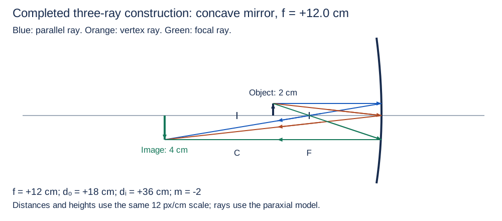
A concave spherical mirror has nonnegative radius of curvature R = 24.0 cm. A real upright object 2.00 cm tall is 18.0 cm in front. Use the paraxial approximation and the real-is-positive convention.
Part a
Determine signed f, dᵢ, m, and hᵢ. State the physical image side, real/virtual type, orientation, and size relative to the object.
f = +12.0 cm; dᵢ = +36.0 cm; m = −2.00; hᵢ = −4.00 cm. The image is in front of the mirror, real, inverted and enlarged by a factor of two.
- f = +R/2 because the spherical mirror is concave.
- 1/dᵢ = 1/12.0 − 1/18.0 = 1/36.0 cm⁻¹.
- m = −dᵢ/dₒ and hᵢ = m hₒ; interpret each sign only after solving.
Scoring criteria
- Credit positive 12.0 cm focus from R/2.
- Credit all three image quantities with signs/units.
- Credit real, inverted, doubled image in front.
Part b
Construct a scaled, arrowed three-principal-ray diagram from the object tip. Mark the vertex, focus, curvature center, and image. Show the parallel ray, the vertex ray, and the focal ray; explain how the actual reflected intersection establishes image type and how its height checks part (a).
The parallel ray reflects through F at 12.0 cm in front; the vertex ray reflects at equal angles to the axis; the ray through F reflects parallel. Their actual leftward reflected paths meet at dᵢ = 36.0 cm and hᵢ = −4.00 cm. Solid reflected paths intersect, so the image is real; it lies below the axis and has twice the object height.
- Use one common scale for distance and height.
- Start all three incident paths at the object tip and put travel arrows toward the mirror.
- Draw reflected arrows away from the mirror and require the three routes to intersect at one point.
- The vertex ray uses equal reflection angles; a center-of-curvature ray would be a different retracing ray.
Scoring criteria
- Credit a real actual diagram with all three principal-ray rules and travel arrows.
- Credit vertex/F/C locations and common image intersection.
- Credit graphical checks of side, real status, inversion and doubled size; prose alone does not earn drawing credit.
Inspect diagram labels
The diagram keeps its full size here. Focus the view and use the arrow keys, or scroll across it, to inspect every label.
Return to the unit problem →Try this problem in its lesson →
A screen image and an apparent image from the same lens
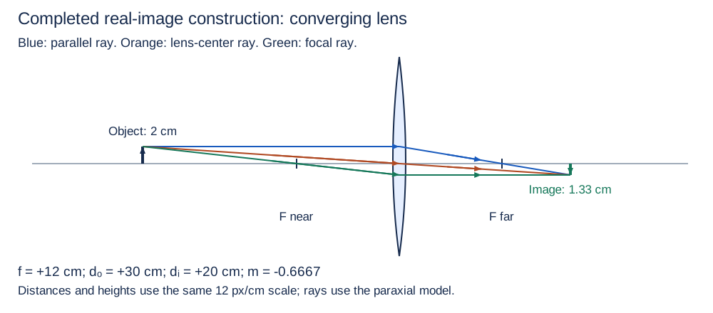
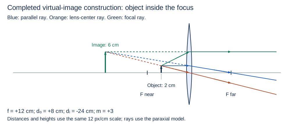
A thin converging lens in air has f = +12.0 cm with the same medium on both sides. Light travels left to right from an upright 2.00 cm object. First dₒ = +30.0 cm; then the object is moved to dₒ = +8.00 cm. Use real-is-positive optical distances.
Part a
For the 30.0 cm object position, calculate dᵢ, m, and hᵢ and construct an arrowed three-principal-ray diagram marking both foci. Determine image side, type, orientation and size, and say where a screen should go. Explain how the actual rays justify the type.
dᵢ = +20.0 cm; m = −2/3; hᵢ = −1.33 cm. The actual transmitted rays meet on the outgoing side, forming a real, inverted, reduced image. Put the screen 20.0 cm to the right of the lens.
- 1/dᵢ = 1/12.0 − 1/30.0 = 1/20.0 cm⁻¹.
- m = −20.0/30.0 and hᵢ = m(2.00 cm).
- Mark foci 12.0 cm on each side. Parallel→far focus, center straight, near focus→parallel all meet at the calculated image tip.
Scoring criteria
- Credit signed numerical distances, magnification and height.
- Credit an actual three-ray drawing with both foci and arrows.
- Credit real status from actual intersection and correct screen placement.
Part b
For the 8.00 cm object position, calculate dᵢ, m, and hᵢ and construct all three principal rays again. Distinguish solid actual transmitted paths from dashed backward extensions. Use the diagram to classify the image and explain how an observer can see it despite the failure of a screen on the image side.
dᵢ = −24.0 cm; m = +3.00; hᵢ = +6.00 cm. Diverging transmitted rays have backward extensions meeting 24.0 cm to the left. The image is virtual, upright and enlarged. An observer on the outgoing side receives the actual diverging rays; no light converges at the virtual point for a screen there.
- 1/dᵢ = 1/12.0 − 1/8.00 = −1/24.0 cm⁻¹.
- m = −(−24.0)/8.00 = +3.00; hᵢ = +6.00 cm.
- The parallel ray heads through the far focus; the center ray stays straight; the ray on the near-focus line exits parallel. Their solid outgoing paths diverge.
- Extend the three outgoing lines backward to a common point; dashed lines are geometry, not reverse light paths.
Scoring criteria
- Credit −24.0 cm, +3.00 and +6.00 cm.
- Credit three correct rays, both foci, distinct solid/dashed paths and virtual intersection.
- Credit virtual/upright/enlarged interpretation and observer-versus-screen explanation.
Inspect diagram labels
The diagram keeps its full size here. Focus the view and use the arrow keys, or scroll across it, to inspect every label.
Inspect diagram labels
The diagram keeps its full size here. Focus the view and use the arrow keys, or scroll across it, to inspect every label.
Return to the unit problem →Try this problem in its lesson →