AP Unit 14 Solutions
Compare your physical setup and reasoning with these worked solutions. A numerical answer is one check; the assumptions, signs, units and representations explain what it means.
Problem 1
A rope pulse travels right past a painted mark; a loudspeaker makes a continuous tone in still air.
Part a
The mark moves transversely about equilibrium as the pulse passes, while the pulse transfers energy right. The tone consists of repeating longitudinal pressure compressions and rarefactions in air.
Why this step? Distinguish material motion, propagation, and repeated versus single disturbances.
Answer and check
The rope requires string material and the tone requires air; neither carries the same material from source to receiver.
Part b
The maximum departure from equilibrium is 101328−101325=3 Pa (also 101325−101322=3 Pa), so the initial pressure amplitude is 3 Pa. Doubling makes it 6 Pa. The initial peak-to-trough range 6 Pa is not the initial amplitude.
Why this step? Determine pressure amplitude relative to equilibrium before comparing energy transfer.
Larger pressure departures mean greater energy transfer and generally greater loudness. Linear-wave intensity scales as pressure amplitude squared, so it becomes four times as large. Warming the same air increases sound speed.
Why this step? Hold frequency and medium fixed for the amplitude comparison, then make a separate medium-temperature comparison.
Answer and check
Initial pressure amplitude 3 Pa, then 6 Pa; generally louder and four times linear-wave intensity at fixed frequency/medium. Sound travels faster after warming the same air.
Scoring and feedback
Problem 2
Two 3.0 m strings each have tension 16 N. String P has mass 0.012 kg and string Q has mass 0.048 kg.
Part a
μP = 0.0040 kg/m and μQ = 0.016 kg/m. Using √(Fₜ/μ), vP = √4000 = 63.2 m/s and vQ = √1000 = 31.6 m/s.
Why this step? Uniform-string mass per length determines speed.
tP = 3.0/63.2 = 0.0474 s; tQ = 3.0/31.6 = 0.0949 s.
Why this step? Travel time is distance divided by propagation speed.
Answer and check
P: 63.2 m/s, 0.0474 s. Q: 31.6 m/s, 0.0949 s.
Part b
Use the same string and marked travel distance, vary known tension, time repeated small pulses, and calculate v. Plot v² against Fₜ; a line through the origin has slope 1/μ.
Why this step? Squaring removes the square root and keeps the medium variable controlled.
Estimate timing scatter and tension uncertainty; avoid changing stretch so much that μ changes appreciably.
Why this step? A feasible test must identify controls and uncertainty.
Answer and check
v² ∝ Fₜ at fixed μ; compare slope with 1/μ.
Part c
String speed depends on tension and mass per length; sound in the same medium travels faster when temperature increases. Radio and visible electromagnetic waves both travel at c = 3.00 × 10⁸ m/s in vacuum.
Why this step? Identify the wave and medium before comparing propagation speeds.
Answer and check
Mechanical speeds depend on medium properties; all vacuum electromagnetic waves share c.
Scoring and feedback
Problem 3
A snapshot of a sinusoidal wave at t = 0 has crests at x = 0.10 m and 0.90 m; its displacement extremes are ±0.015 m. A fixed-point trace repeats every 0.20 s.
Part a
A = 0.015 m, λ = 0.80 m, T = 0.20 s, f = 5.0 Hz. Then v = fλ = 4.0 m/s.
Why this step? Read spatial and temporal repeat separately.
starts at maximum displacement.
Why this step? A cosine with angular coefficient 2πf matches the stated start.
Answer and check
0.015 m, 0.80 m, 0.20 s, 5.0 Hz, 4.0 m/s; y = 0.015 cos(10πt) m.
Part b
Place extremes at ±0.015 m. Spatial crests repeat every 0.80 m; temporal crests repeat every 0.20 s. A vertical rescaling changes only amplitude.
Why this step? Frequency and wavelength are measured along the horizontal axes.
Answer and check
The two sinusoidal sketches have different horizontal units; amplitude is independent of their repeat intervals.
Scoring and feedback
Problem 4
Two generators drive identical ideal strings at equal displacement amplitude. Generator R has 6 Hz; generator S has 12 Hz. The strings carry waves at 18 m/s.
Part a
TR = 1/6 s and TS = 1/12 s; λR = 18/6 = 3.0 m and λS = 18/12 = 1.5 m. Equal amplitude and medium imply greater energy transfer for S; sinusoidal-string average power is four times R.
Why this step? The fixed string medium preserves v, while mechanical power scales as f² at equal amplitude.
Answer and check
S has half the period, half the wavelength, and greater mechanical energy transfer.
Part b
S at 960 Hz has the higher pitch. Increase R’s sound pressure amplitude at fixed 480 Hz to make it louder without changing pitch.
Why this step? Pitch follows repetition rate; loudness depends strongly on amplitude.
Answer and check
S at 960 Hz is higher pitched; increasing R’s amplitude at 480 Hz changes loudness independently.
Scoring and feedback
Problem 5
A 20 Hz wave travels from a string with μ = 0.020 kg/m to one with μ = 0.0050 kg/m; both have tension 8.0 N.
Part a
v₁ = √(8/0.020) = 20 m/s and v₂ = √(8/0.0050) = 40 m/s. Frequency remains 20 Hz, giving λ₁ = 1.0 m and λ₂ = 2.0 m.
Why this step? Use each medium’s μ and the same source frequency.
Entering the faster string produces a noninverted reflected pulse, traveling back in string 1.
Why this step? For this equal-tension string junction, lighter/faster entry gives no reflection phase reversal.
Answer and check
20 m/s and 40 m/s; 1.0 m and 2.0 m; noninverted reflection.
Part b
A partial boundary reflection can coexist with transmission. In a lossless junction the incident energy is divided between reflected and transmitted waves; reflection does not imply all energy returns.
Why this step? Distinguish complete reflection at a limiting boundary from partial reflection at a junction.
Answer and check
The claim is false; the junction generally produces both waves.
Part c
The incident speed is now 40 m/s in the light string. Transmission enters the heavy string at 20 m/s; its lower speed at equal tension means the reflected pulse is inverted, so its displacement is downward.
Why this step? The heavier-string junction is the slower-medium case in the stated string model.
The reflected pulse returns through the light string at 40 m/s. Reflection changes its direction and displacement phase, not the wave speed of the medium it remains in.
Why this step? Separate the reflected medium from the transmitted medium.
Answer and check
Downward/inverted reflection at 40 m/s; transmission into the heavy string at 20 m/s.
Scoring and feedback
Problem 6
Unpolarized light of intensity 80 W/m² crosses an ideal vertical polarizer and then an ideal analyzer at 60° to vertical. The final beam illuminates 0.015 m².
Part a
The first polarizer gives 40 W/m². The analyzer gives 40 cos²60° = 10 W/m². Pavg = IS = (10)(0.015) = 0.15 W.
Why this step? Ideal unpolarized transmission halves intensity; the second filter selects the surviving field component.
Intensity averages power per area over oscillations; it is not an instantaneous peak power density.
Why this step? Fields and energy flow oscillate, so a period average is used.
Answer and check
10 W/m² and 0.15 W.
Part b
Horizontal is perpendicular to the transmitted vertical E, so ideal transmission is zero. Longitudinal air sound has no transverse oscillation plane to select, so crossed slots do not provide the same polarization mechanism.
Why this step? Polarization concerns orientation of transverse disturbance, not travel direction.
Answer and check
Crossed light axes block ideally; longitudinal sound cannot be polarized this way.
Part c
Reflection can preferentially select electric-field orientations, making the beam polarized or partly polarized. A rotating analyzer then selects different components, changing intensity. Refraction through a medium or passage through suitable openings can also select transverse orientations.
Why this step? Polarization is selection among directions perpendicular to propagation.
Air sound is longitudinal and has no such transverse orientation choices, so this light observation does not extend the polarization mechanism to sound.
Why this step? Disturbance direction relative to travel decides whether polarization is possible.
Answer and check
Reflection, refraction, and suitable openings can polarize transverse waves; longitudinal sound cannot be polarized by selecting a transverse plane.
Scoring and feedback
Problem 7
A vacuum beam has wavelength 0.030 m and travels along +x. Its E field points along +z at one instant.
Part a
f = (3.00 × 10⁸)/0.030 = 1.0 × 10¹⁰ Hz. B may point along −y for propagation +x. A constant-phase wavefront is a y–z plane.
Why this step? E × B gives the travel direction; the fields lie in the wavefront plane.
Answer and check
1.0 × 10¹⁰ Hz, with E and B transverse and mutually perpendicular.
Part b
No. The wave consists of fields and does not require vibrating material particles. Its vacuum speed remains c.
Why this step? Identify the electromagnetic carrier rather than importing mechanical-wave requirements.
Answer and check
The beam propagates through vacuum.
Scoring and feedback
Problem 8
An observatory detects radio, microwave, infrared, visible, ultraviolet, X-ray, and gamma radiation from a source.
Part a
The requested order is radio, microwave, infrared, visible, ultraviolet, X-ray, gamma. Within visible it is red, orange, yellow, green, blue, violet.
Why this step? These categories follow wavelength across the continuous electromagnetic spectrum.
Answer and check
Longest to shortest follows the listed category and color orders.
Part b
They have the same speed c and travel time D/c. Gamma has greater f because its λ is smaller. The ordering supports that comparison without a memorized numerical boundary.
Why this step? Use c = fλ and the common vacuum speed.
Light often means visible electromagnetic radiation, but the term can also refer to electromagnetic radiation across all wavelengths.
Why this step? State which convention is intended rather than changing the physical model.
Answer and check
Equal travel time; gamma has higher frequency. AP requires order, not exact cutoff values.
Scoring and feedback
Problem 9
A subsonic ambulance passes a stationary listener in still air. The siren’s source frequency stays constant.
Part a
Before passage, advancing emission points crowd fronts on the listener’s side, giving higher observed f. After passage, fronts arriving behind the departing source are farther apart, giving lower f.
Why this step? Observed rate follows front spacing while sound speed in the air remains approximately constant.
Answer and check
Higher on approach; lower on recession.
Part b
Faster source motion changes each emission position by more, so front compression/expansion and frequency shifts are greater. More amplitude affects loudness, not front repetition.
Why this step? Keep the source frequency and geometry fixed for the velocity comparison.
Answer and check
Greater speed strengthens both approach and recession shifts.
Scoring and feedback
Problem 10
A siren and listener move to the right in still air, both at subsonic speeds relative to the air, with the listener ahead of the siren. Consider three cases: same velocity; siren faster; listener faster.
Part a
Same velocity: the effects cancel and observed f equals rest f. Siren faster: their separation shrinks and the observer encounters fronts at a higher rate than source timing after both motion effects. Listener faster: separation grows and observed f is lower.
Why this step? Both velocities must be referred to the medium in this straight-line subsonic setup.
Answer and check
Same: equal; siren faster: greater; listener faster: smaller.
Part b
No. Source velocity changes wavelength in air; observer velocity changes how fast fronts are crossed. Equal closing speed alone does not fix both quantities. A quantitative formula is not required to identify this distinction.
Why this step? The sound medium defines two distinct mechanisms rather than a single universally sufficient relative-speed input.
Answer and check
No guarantee; specify source and observer motion relative to the medium.
Scoring and feedback
Problem 11
At t = 0 two pulses overlap. At positions x = 0,1,2,3,4 cm their displacements are P = [0,2,4,2,0] mm and Q = [0,−2,−4,−2,0] mm.
Part a
At every listed point P + Q = 0, so the net displacement graph lies on equilibrium at this instant. In the linear model both pulses subsequently reappear with their original shapes and directions.
Why this step? Superposition adds signed displacement; it does not erase the disturbances or make them bounce.
Answer and check
Zero displacement during exact overlap; the pulses continue after it.
Part b
Q becomes [0,−1,−2,−1,0] mm, giving net [0,1,2,1,0] mm. The signs oppose wherever nonzero, so the overlap is destructive even though cancellation is incomplete.
Why this step? Destructive describes opposing contributions, not a requirement of zero result.
Answer and check
Net [0,1,2,1,0] mm; destructive and incomplete.
Part c
Q is [0,1,2,1,0] mm, giving net [0,3,6,3,0] mm. Both displacements have the same sign wherever nonzero, so this is constructive interference; the net peak is 6 mm.
Why this step? Add signed displacements point by point and identify same-direction contributions.
Answer and check
Constructive overlap; net displacement [0,3,6,3,0] mm and peak 6 mm.
Scoring and feedback
Problem 12
A 0.60 m string fixed at both ends has wave speed 120 m/s. A tuning fork pair produces tones at 500 Hz and 504 Hz.
Part a
The fixed string requires L = nλ/2: fundamental λ = 1.20 m, f = 100 Hz; third λ = 0.40 m, f = 300 Hz. The third has nodes at 0,0.20,0.40,0.60 m and antinodes halfway between.
Why this step? Like boundaries fit integer half wavelengths.
A closed–open pipe requires odd quarter wavelengths: f₁ = 120/(4 × 0.60) = 50 Hz, then 150 Hz, 250 Hz, … .
Why this step? Unlike displacement boundaries allow only odd harmonics.
Answer and check
String: 100 and 300 Hz; closed–open pipe fundamental 50 Hz and only odd multiples.
Part b
fbeat = |504 − 500| = 4 Hz. The fork phases repeatedly align and oppose, giving loudness maxima four times per second.
Why this step? Different repetition rates cause a recurring phase difference.
Answer and check
4 Hz; the resultant amplitude changes as the tones move into and out of phase.
Part c
The fixed–loose string has a displacement node at x=0 and an antinode at x=L, so its fundamental has λ=4L=2.40 m and f=120/2.40=50 Hz.
Why this step? Opposite boundary types fit one quarter wavelength.
The open–open pipe has displacement antinodes at both ends and one interior node in its fundamental; λ=2L=1.20 m and f=100 Hz.
Why this step? Like boundary types fit one half wavelength even though they are both antinodes rather than nodes.
A loose–loose string has displacement antinodes at both ends, like the open–open pipe; its fundamental also has λ=2L and f=100 Hz at the same wave speed.
Why this step? The boundary type, rather than whether the medium is string or air, sets this wavelength condition.
Answer and check
Fixed–loose string: 50 Hz; open–open pipe: 100 Hz. Label displacement, because pipe pressure nodes/antinodes are complementary.
The loose–loose string also has a 100 Hz fundamental.
Scoring and feedback
Problem 13
For a single slit, λ = 500 nm, a = 0.10 mm, and screen distance L = 1.0 m.
Part a
y₁ = λL/a = 0.0050 m and y₂ = 0.010 m. The symmetric values are ±5.0 mm and ±10 mm. Central width is 10 mm.
Why this step? Dark orders are nonzero integers; the central width spans the two first minima.
The largest |y|/L is 0.010, so θ ≈ 0.57°, safely below 10°.
Why this step? Check geometry before using the approximation.
At u=0 the slit contributions reinforce, so the center is a maximum. Its bounding minima are u=±1, making central width 2 in u; a side lobe lies between consecutive nonzero minima and has width 1 in u. This maps to twice the neighboring dark-order interval on the small-angle screen.
Why this step? Read the curve’s zero positions and distinguish the central bright interval from side lobes.
Answer and check
Minima at ±5.0 and ±10 mm; central width 10 mm.
The plot has central maximum u=0, first dark orders u=±1, and central bright interval twice a side-lobe interval.
Part b
Edge-to-edge path difference is a sin θ = λ. Points separated by a/2 differ in path by λ/2, so corresponding contributions from the two halves oppose.
Why this step? A single opening contains many contributing wavefront locations.
Answer and check
The paired half-slit contributions cancel, producing the first dark band.
Scoring and feedback
Problem 14
A class compares diffraction through a long narrow slit, a circular pinhole, and a doorway using visible light and sound.
Part a
Sound wavelengths can be comparable to a doorway and spread strongly around its edges. Visible wavelengths are much smaller, so most doorway transmission travels nearly straight. A narrow slit spreads most across its narrow width and makes bands; a circular pinhole makes a circular pattern.
Why this step? Diffraction strength depends on relative size and its pattern depends on aperture shape.
Answer and check
Stronger relative diffraction for opening size near λ; slit bands versus circular rings.
Part b
Use one laser and fixed L; measure symmetric first-minimum positions for several known a values. Plot half the central width against 1/a; slope predicts λL. Repeat measurements and use the band width/center uncertainty as horizontal-position uncertainty.
Why this step? The model predicts an inverse-width comparison, while symmetric measurements reduce center offset.
Keep incidence normal, brightness suitable, and angles small; terminate the beam below eye level.
Why this step? These controls preserve the same model and a safe measurement setup.
Answer and check
A linear plot against 1/a supports wider patterns for narrower slits.
Scoring and feedback
Problem 15
Two slits each have width a = 0.10 mm and separation d = 0.40 mm. Light wavelength is 600 nm and L = 2.0 m.
Part a
Δy = λL/d = 3.0 mm. The envelope first zero is at |y| = λL/a = 12 mm.
Why this step? Separation d sets fine interference; width a sets the envelope.
The fourth interference maximum would be at 4 × 3.0 = 12 mm, coinciding with an envelope zero, so m = ±4 is missing.
Why this step? A zero envelope suppresses an otherwise allowed interference maximum.
Answer and check
3.0 mm spacing; first envelope zeros ±12 mm; fourth order missing.
Part b
Draw fine approximately equally spaced peaks under a broad central envelope, fading toward zeros at ±12 mm. Interference requires phase-sensitive superposition, a wave property demonstrated by Young’s experiment.
Why this step? The combined pattern has two geometric scales and alternating reinforcement/cancellation.
Answer and check
Fine maxima/minima within a broad envelope provide wave-behavior evidence.
Part c
The extra path from one slit is the projection of separation onto the outgoing direction: . In-phase slit contributions reinforce when .
Why this step? An integer number of cycles brings the two contributions back to the same phase.
For small θ, sin θ ≈ tan θ = ymax/L, giving . Opposing phase occurs at .
Why this step? Screen geometry connects angular path difference with measured position; a half-integer cycle gives opposition.
Answer and check
Bright: d sin θ=mλ and ymax≈mλL/d at θ<10°. Dark interference: d sin θ=(m+1/2)λ.
Scoring and feedback
Problem 16
White light falls on a grating with 400 lines/mm. Consider red λ = 650 nm and violet λ = 400 nm.
Part a
d = 1/(4.00 × 10⁵) = 2.50 × 10⁻⁶ m. θred = asin(0.260) = 15.1°; θviolet = asin(0.160) = 9.21°.
Why this step? Use exact sin θ = mλ/d for the grating.
m = 0 sends all wavelengths straight ahead, so the center is white.
Why this step? Zero path difference reinforces every color at the same direction.
Answer and check
Red 15.1°, violet 9.21°; center white and red farther out.
Part b
mmax is the largest integer ≤ d/λ: red 3, violet 6. Adding slits at unchanged spacing sharpens the maxima but preserves d sin θ = mλ.
Why this step? Order existence follows |sin θ| ≤ 1; slit number changes peak sharpness rather than adjacent path difference.
Answer and check
Red: 3; violet: 6. More slits do not change the principal directions.
Scoring and feedback
Problem 17
A soap film (n = 1.33) in air is illuminated normally with vacuum wavelength 532 nm. Absorption is negligible.
Part a
The air→film reflection reverses by π; the film→air reflection does not. With one relative reversal, 2nt = λ₀/2 gives t = 532/(4 × 1.33) = 100 nm.
Why this step? Travel must supply a half-cycle to compensate the one reflection reversal.
At each interface some incident light reflects and some transmits. Absorption is neglected here, so energy carried by reflected and transmitted light accounts for the incident energy at a lossless boundary.
Why this step? The phase calculation still needs the reflected/transmitted energy pathways to identify the two returning waves.
Answer and check
Top π, bottom zero; t = 100 nm.
Part b
One-reversal destructive phase uses 2nt = mλ₀. The smallest positive case m = 1 gives t = 532/(2 × 1.33) = 200 nm.
Why this step? A full-cycle travel phase leaves the reflection reversal uncompensated.
For white light different thicknesses satisfy reinforcement for different λ₀; the observed reflected color therefore varies across the film.
Why this step? Film colors come from wavelength-dependent superposition.
Air→oil and oil→water both increase index, so both reflections reverse and their relative reflection phase is zero. The soap film has only one reversal. The constructive/destructive travel conditions therefore swap between these two stacks, but varying oil thickness still changes 2nt/λ₀ and can reinforce different reflected colors.
Why this step? Oil colors need both film thickness and the actual underlying index; soap’s one-reversal rule cannot be assumed for every oil film.
Answer and check
200 nm for destructive phase at 532 nm; changing thickness selects different colors.
Part c
For a steady interface, incident power is reflected plus transmitted plus absorbed. Thus Pabs=100−12−68=20 mW.
Why this step? The portion that does not leave in either beam becomes energy transferred to the material.
Answer and check
20 mW is absorbed; 12% reflects, 68% transmits, and 20% is absorbed.
Scoring and feedback
Problem 18
An antireflection coating with n = 1.40 is placed on glass of n = 1.96, surrounded by air. Its design vacuum wavelength is 560 nm at normal incidence.
Part a
Both reflections are lower-to-higher index and reverse by π; relative reflection phase is zero. Set 2nt = λ₀/2, so t = 560/(4 × 1.40) = 100 nm.
Why this step? Two reversals require a half-cycle extra travel phase for opposition.
1.40 = √(1.00 × 1.96), giving matching ideal reflected amplitudes.
Why this step? Opposite phases alone do not guarantee zero net field.
Refraction/transmission adds no abrupt reflection reversal in this model. Travel within the coating accumulates the propagation phase used in the optical-path calculation.
Why this step? No transmission reversal does not mean no phase accumulated during travel.
Answer and check
100 nm; two π reversals, half-cycle travel phase, matching amplitudes.
Part b
Changing λ₀ changes 2nt/λ₀; changing angle changes the optical travel path. The two reflected fields generally cease to oppose exactly, so the reflection can increase. Numerical AP thin-film analysis here is limited to normal incidence.
Why this step? The interference condition applies to a specific design geometry and wavelength.
Answer and check
The coating is selective in wavelength and angle; oblique-angle discussion is qualitative.
Scoring and feedback
Problem 19
A class measures standing waves on a uniform 1.00 m string fixed at both ends. Its mass is 0.0100 kg. Fundamental frequencies for tensions 4.0, 9.0, and 16.0 N are 10.0, 15.0, and 20.0 Hz.
Part a
v = 2Lf₁ and v² = Fₜ/μ give f₁² = Fₜ/(4L²μ). Plot f₁² against tension. μ = 0.0100 kg/m, so slope = 1/(4 × 1.00² × 0.0100) = 25.0 Hz²/N.
Why this step? Combine boundary length with propagation speed before selecting graph axes.
The data give (4,100), (9,225), (16,400), all on a line of slope 25.0 through the origin.
Why this step? Transform each measured value and compare with the prediction rather than eyeballing f versus tension.
Answer and check
The squared-frequency plot supports both models with slope 25.0 Hz²/N.
Part b
Sweep frequency on both sides of the amplitude maximum, record the interval of near-resonance behavior, and repeat. Measure length and tension independently. A nominal end that moves appreciably violates a displacement node; the mode spacing or node placement can differ from the fixed–fixed prediction.
Why this step? A model test checks its boundaries as well as numerical fit.
Answer and check
Use repeat resonance sweeps, explicit uncertainty intervals, and observed end motion.
Scoring and feedback
Problem 20
A double-slit experiment gives bright maxima at y = 0, ±3.0, ±6.0 mm, with L = 1.20 m and d = 0.20 mm. Its first envelope zeros occur at ±12 mm.
Part a
λ = Δyd/L = (0.0030)(0.00020)/1.20 = 5.0 × 10⁻⁷ m = 500 nm. a = λL/0.012 = 5.0 × 10⁻⁵ m = 0.050 mm.
Why this step? Use fine spacing for d and envelope zero for a.
m = 12/3 = 4 is missing. The 500 nm light has f = 6.0 × 10¹⁴ Hz, greater than the 650 nm light’s 4.62 × 10¹⁴ Hz.
Why this step? The envelope zeros remove an interference order; inverse wavelength sets vacuum frequency.
Answer and check
λ = 500 nm, a = 0.050 mm, missing fourth order; higher f than 650 nm light.
Part b
Use the separation of symmetric ±m features divided by 2, and use differences between neighboring maxima. A common center offset cancels in these differences. A one-sided y measured from the wrong center biases λ or a; L and slide tolerances remain separate uncertainties.
Why this step? Choose measured differences that reject the shared offset.
Answer and check
Symmetric-pair and adjacent-fringe differences reduce the center offset.
Scoring and feedback
Problem 21
A 600 nm vacuum laser crosses a polarizer, then a normal-incidence coating (n = 1.50) on glass (n = 2.25), and is analyzed with a grating of spacing 2.0 μm in air.
Part a
f = c/λ₀ = 5.0 × 10¹⁴ Hz. λfilm = λ₀/n = 400 nm. Both coating reflections reverse, and t = λfilm/4 = 100 nm; √(1 × 2.25) = 1.50 matches amplitudes.
Why this step? Source timing stays fixed while speed and wavelength change in the coating.
The polarizer changes transmitted intensity/orientation; a stationary interface changes speed and wavelength but preserves frequency.
Why this step? Do not assign a frequency change to filtering or refraction.
Answer and check
5.0 × 10¹⁴ Hz, 400 nm, and 100 nm.
Part b
sin θ = 600 nm/2000 nm = 0.300, so θ = 17.5°. Rotating the filter changes brightness but not wavelength, so it does not move the principal grating direction if light remains transmitted.
Why this step? The path condition uses wavelength and spacing, not amplitude.
Answer and check
17.5°; ideal polarization rotation changes brightness rather than order position.
Scoring and feedback
Explain and apply: worked solutions
Compare the physical setup and the reasoning, as well as the final answer. Give credit for equivalent correct reasoning, using the rubric to find your next step.
Identify the repeating model from observations
A speaker emits a sustained pure tone in still air. A fixed pressure sensor records equal-phase maxima every 0.0100 s. A simultaneous spatial pressure map shows successive compressions 3.40 m apart. The speaker is then switched off and makes one short isolated click.
Part a
State the appropriate continuous-wave model for the sustained tone, explicitly identify its well-defined wavelength and frequency from the two observations, and calculate propagation speed. Explain why the fixed-location measurement and snapshot cannot exchange their horizontal units.
The sustained tone is modeled as a continuous periodic disturbance with λ = 3.40 m and f = 100 Hz, giving v = 340 m/s. Seconds between repeats determine period/frequency; metres between equal-phase locations determine wavelength.
- Read T = 0.0100 s from the time sensor, not from the spatial map.
- Compute f = 1/T = 100 Hz and read λ = 3.40 m.
- Multiply fλ; Hz·m = m/s.
Scoring criteria
- Credit the explicit continuous periodic model and both well-defined properties.
- Credit correct f, λ and v with units.
- Credit separate temporal and spatial meanings.
Part b
Compare the isolated click with the sustained tone: state which is a pulse and why assigning the click one repeating crest spacing and cycle rate is not justified by these observations. Describe local air-particle motion relative to propagation and explain why sound does not carry those same particles from the speaker to the sensor.
The isolated click is a single pressure disturbance or pulse. Its shape may contain several frequency components, but no sustained periodic train is supplied to define one repeating wavelength and cycle rate. In air, particle disturbance is longitudinal, back and forth about equilibrium parallel to propagation; interactions transfer energy without bulk transport of the same air particles.
- Distinguish one disturbance from repeated cycles.
- Do not conclude the click has no possible spectral components; conclude the single periodic model is not established.
- Describe longitudinal local oscillation and neighbor-to-neighbor energy transfer.
Scoring criteria
- Credit single-pulse identification and lack of evidence for one repeating f/λ.
- Credit parallel local particle oscillation.
- Credit transferred energy without bulk transport of the same particles.
Return to the unit problem →Try this problem in its lesson →
Write and draw two views of the same traveling wave
A sinusoidal wave travels right on a uniform ideal string. Displacement extremes are ±3.00 mm. Adjacent crests are 1.20 m apart; a marked segment repeats every 0.400 s. At t = 0 a crest is at x = 0.300 m. Use x in metres, t in seconds and y in millimetres.
Part a
Determine A, λ, T, f and v. Write a fixed-location displacement-time equation at x = 0.300 m starting at a crest, and a fixed-time displacement-position equation at t = 0.100 s. Keep the given phase origin and rightward direction consistent.
A = 3.00 mm, λ = 1.20 m, T = 0.400 s, f = 2.50 Hz and v = 3.00 m/s. At x = 0.300 m: y(t) = (3.00 mm) cos(5πt), with 5π in rad/s. At t = 0.100 s: y(x) = (3.00 mm) cos[2π((x−0.300 m)/(1.20 m)−0.250)] = (3.00 mm) sin[2π(x−0.300 m)/(1.20 m)].
- Use A as the maximum departure, not the 6.00 mm peak-to-trough range.
- f = 1/0.400 = 2.50 Hz and v = fλ = 3.00 m/s.
- Start from y(x,t) = (3.00 mm) cos[2π((x−0.300 m)/(1.20 m)−t/(0.400 s))].
- Freeze x for the first equation and t for the second; t/T = 0.250 adds a quarter-cycle shift.
Scoring criteria
- Credit all five physical quantities and units.
- Credit an explicit displacement-time equation at the specified location.
- Credit an explicit displacement-position equation at the specified time with correct phase.
Part b
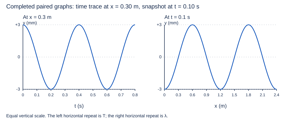
Create the actual y-versus-t graph at x = 0.300 m from 0 to 0.800 s and the actual y-versus-x snapshot at t = 0.100 s from 0 to 2.40 m. Label axes, numerical scales, units, extrema and zero crossings. Locate the first nonnegative spatial crest on the snapshot and use its shift from t = 0 to check v.
The time curve has maxima at t = 0, 0.400, 0.800 s; minima at 0.200 and 0.600 s; zeros at 0.100, 0.300, 0.500, 0.700 s. The snapshot has crests at x = 0.600 and 1.80 m; troughs at 0, 1.20, 2.40 m; zeros at 0.300, 0.900, 1.50, 2.10 m. Extrema are ±3.00 mm. The first crest shifted +0.300 m in 0.100 s, giving +3.00 m/s.
- Plot several quarter-cycle points for each equation.
- Use time units for the first horizontal axis and position units for the second.
- Draw smooth sinusoids through all extrema/zeros; do not substitute point lists for the requested graphs.
- Track the original crest at x = 0.300 m to x = 0.600 m.
Scoring criteria
- Credit both actual complete graphs and labeled scales/units.
- Credit extrema and zero crossings consistent with the equations.
- Credit positive crest shift and numerical velocity check.
Part c
The source doubles displacement amplitude on the unchanged ideal string but keeps its frequency fixed. Predict changes in both graphs, their horizontal repeats, and wave speed. Then explain why an antinode of a later standing wave would not mean a point stays at maximum displacement.
Both vertical extrema become ±6.00 mm. Period remains 0.400 s, wavelength 1.20 m and speed 3.00 m/s in the unchanged linear string model. An antinode is a location of maximum oscillation amplitude; its instantaneous displacement varies and crosses zero.
- Separate vertical amplitude from source timing and the medium’s speed.
- With f and v fixed, λ = v/f stays fixed.
- Distinguish maximum possible displacement at an antinode from its displacement at one instant.
Scoring criteria
- Credit doubled vertical amplitude and unchanged horizontal repeats/speed.
- Credit fixed-frequency/medium justification.
- Credit antinode amplitude-versus-instantaneous-displacement distinction.
Inspect diagram labels
The diagram keeps its full size here. Focus the view and use the arrow keys, or scroll across it, to inspect every label.
Return to the unit problem →Try this problem in its lesson →
Build a standing wave instead of assuming one
A 1.50 m ideal string is fixed at both ends. Two steady sinusoidal traveling contributions confined to the string are yᵣ = (1.50 mm) sin[2πx/(1.00 m) − 80πt] and yₗ = (1.50 mm) sin[2πx/(1.00 m) + 80πt], with t in seconds. Use sin(a−b)+sin(a+b) = 2 sin a cos b. The separate waves propagate in opposite directions.
Part a
Add the displacements to obtain y(x,t), and explain why two waves traveling in opposite directions within the confined region can form a standing pattern. Verify that the sum satisfies both fixed endpoints at every time, even though each separate contribution need not vanish at an endpoint.
y(x,t) = (3.00 mm) sin[2πx/(1.00 m)] cos(80πt). Its spatial sine factor stays fixed while the cosine varies in time. At x = 0 and 1.50 m, sin 0 = sin 3π = 0, so the sum is zero for every t. The component contributions cancel there; neither component alone is the complete boundary-satisfying displacement.
- Apply the supplied addition identity to equal-amplitude waves with opposite travel phase signs.
- Identify fixed spatial amplitude factor and common time factor.
- Substitute each boundary into the sum, or show their separate contributions cancel.
Scoring criteria
- Credit exact sum with amplitude, phase and units.
- Credit opposite traveling interference confined by boundaries as the formation mechanism.
- Credit both endpoint checks valid for all times.
Part b
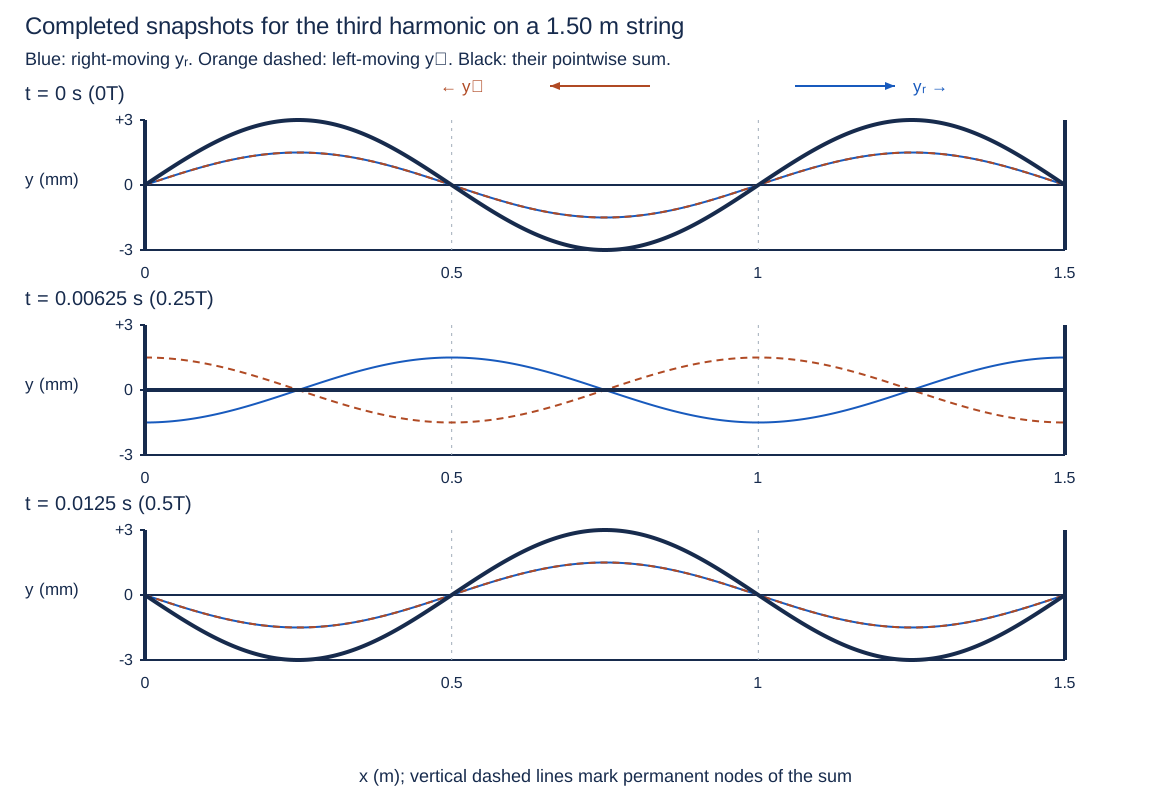
Draw the separate right-moving and left-moving profiles and their pointwise sum over the full string at t = 0, T/4 and T/2. Use a common vertical scale in millimetres and horizontal scale in metres. Compute the three times, label permanent nodes/antinodes, and explain why the all-zero snapshot at T/4 does not make every point a node.
f = 80π/(2π) = 40.0 Hz; T = 0.0250 s, so the times are 0, 0.00625, 0.0125 s. At t = 0, both components are 1.50 sin(2πx/1.00 m) mm and the sum is 3.00 sin(2πx/1.00 m) mm. At T/4 the components are −1.50 cos(2πx/1.00 m) and +1.50 cos(2πx/1.00 m) mm, with zero sum. At T/2 both components reverse their initial sine profiles; the sum reverses too. Nodes are 0, 0.500, 1.00, 1.50 m; antinodes are 0.250, 0.750, 1.25 m. Only nodes stay zero for every t; antinodes pass through equilibrium.
- Extract f and T from the time coefficient.
- Evaluate the component equations at phases 0, π/2 and π.
- Plot all three traces on each common set of axes.
- Determine nodes from the fixed sine zeros, antinodes from |sin| = 1.
Scoring criteria
- Credit three actual common-scale plots, component directions and signed pointwise sums.
- Credit all times, nodes and antinodes.
- Credit time-independent node definition and antinode oscillation through zero.
Part c
Use the diagram’s node spacing to determine λ. Calculate v, identify the harmonic number, and determine the fundamental frequency. Explain why changing the right endpoint from fixed to ideally loose changes the allowed standing patterns.
Adjacent nodes are 0.500 m apart, so λ = 1.00 m. v = fλ = 40.0 m/s. L = 3λ/2 gives n = 3; f₁ = v/(2L) = 13.3 Hz. With a loose right end, that end must be a displacement antinode instead of a node; the previous pattern fails that boundary. Fixed–loose patterns contain odd quarter wavelengths and have f₁ = v/(4L) = 6.67 Hz at the same v.
- Read λ/2 from adjacent permanent nodes.
- Use wave speed and integer half-wavelength fit independently.
- Change the right boundary to an antinode and count odd quarter wavelengths.
Scoring criteria
- Credit λ = 1.00 m, v = 40.0 m/s, third harmonic and f₁ = 13.3 Hz.
- Credit invalidity of the old pattern at the new loose boundary.
- Credit fixed–loose odd-quarter-wave pattern and 6.67 Hz fundamental.
Inspect diagram labels
The diagram keeps its full size here. Focus the view and use the arrow keys, or scroll across it, to inspect every label.
Return to the unit problem →Try this problem in its lesson →
Diagnose a time axis mistaken for a spatial axis
At x = 0, a string wave is y(t) = (2.00 mm) cos(20πt), with t in seconds. A t = 0 snapshot is y(x) = (2.00 mm) cos(4πx), with x in metres.
Part a
Which interpretation is consistent with both equations?
f = 10.0 Hz, λ = 0.500 m and v = 5.00 m/s.
- 20π = 2πf, so f = 10.0 Hz.
- 4π = 2π/λ, so λ = 0.500 m.
- v = fλ = 5.00 m/s.
Scoring criteria
- Credit the correct interpretation and correct angular-coefficient conversion for each axis.
Return to the unit problem →Try this problem in its lesson →