Bernoulli’s Equation
Original textbook reading.
Use continuity and Bernoulli for steady incompressible ideal flow in filled pipes. The new AP lessons add pressure, Pascal's principle and the model limits.
In this section we will learn about everything dealing with fluid flow through a pipe. More specifically, we will cover Bernoulli’s Equation and a little bit of the concept behind it.
Imagine a pipe with some volume. There is a certain amount of fluid with an area and velocity and the same amount of fluid with a velocity and area . The color is used to coordinate with the image so don’t get confused. Ever notice that when you place a finger over the outlet of the hole on a hose, the water velocity increases?
The same can be applied to any pipe. Take for example in the figure. If the blue fluid were to enter from the left side for a certain time with an area and velocity (assuming the flow is steady state and we are dealing with an incompressible fluid) then the same volume of orange fluid must emerge from the right side. The only difference is that the values are all inversely proportional to one another. Meaning that if then and vice versa.
Figure 8.2.1 Equation of Continuity
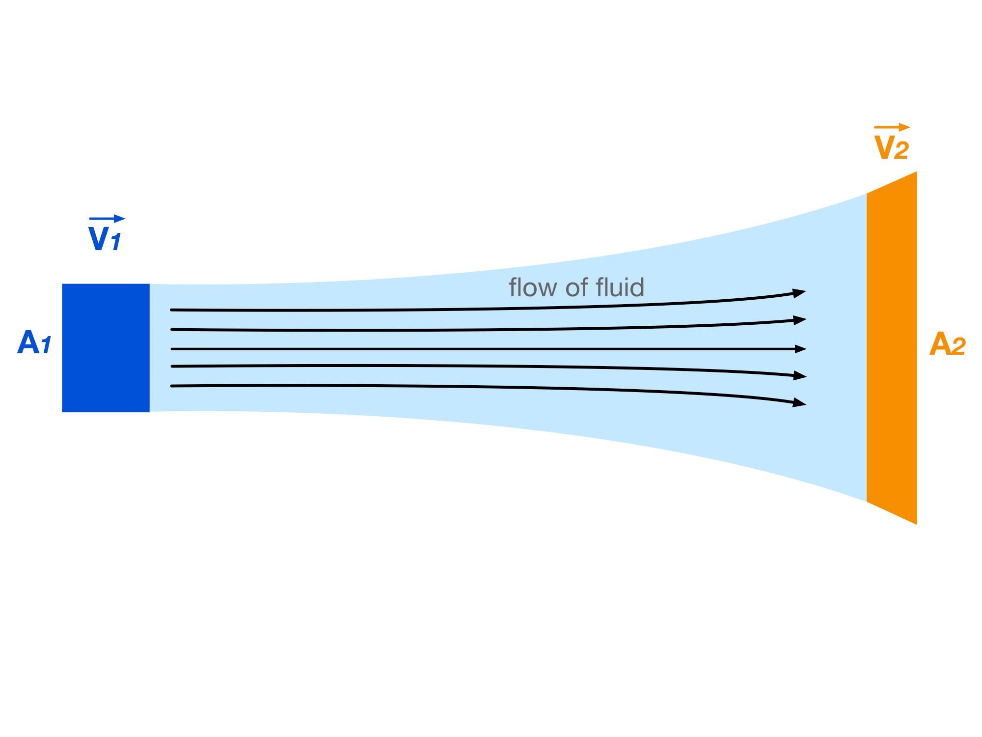
This is the concept behind the equation of continuity. That the same volume of fluid entering from one side is emerging from the other side. The equation associated with this is:
A₁v₁ = A₂v₂ (Equation 8.2.1), where v₁ and v₂ are mean speeds normal to their respective cross-sections. This is the steady incompressible form of mass continuity.
Example Problem 8.2.1
A horizontal tapering pipe has inlet diameter 4 m and outlet diameter 2 m. A fluid particle travels 7 m through it with constant acceleration 3 m/s² along the flow. Assume steady incompressible flow with a smoothly varying area compatible with that acceleration. Find its inlet speed.
Example Problem 8.2.1
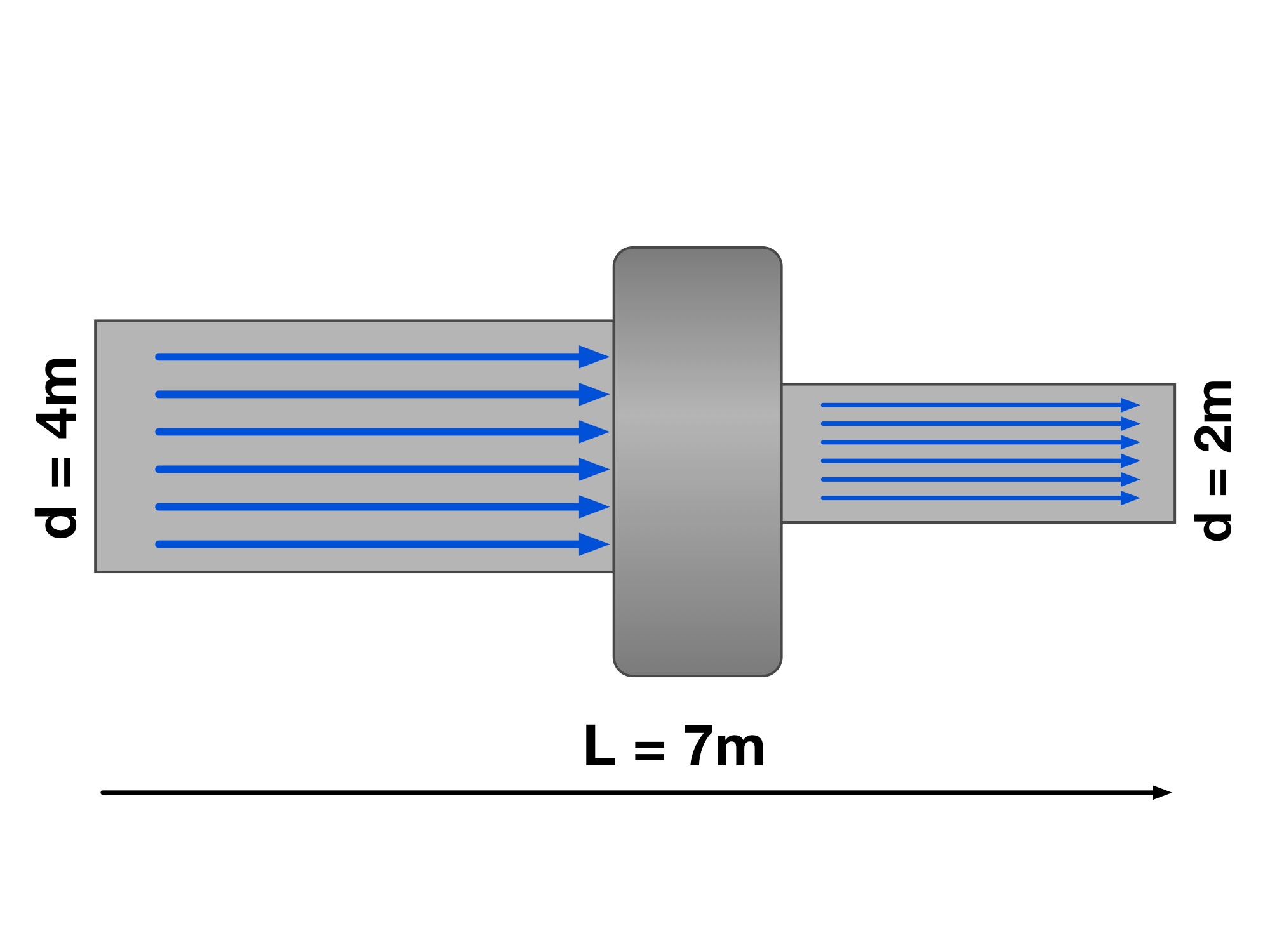
Step 1: Realize that this problem is a continuity equation
Even before tackling the problem, think about it conceptually. A fluid is traveling through a pipe with a velocity . The pipe diameter changes from bigger to smaller, therefore the the cross sectional area goes from bigger to smaller as well. This change in area means that the velocity will increase. To keep the same volume flow rate through the pipe, the velocity will have to increase through the pipe with a smaller diameter.
Step 2: Use the continuity equation
where is the area of a circle in this case since we have a pipe. We are given the diameter so in order to solve for the area, we need the
radius. Since :
And simplifying it even further will give us:
Step 3: Use of kinematics
Since this fluid is accelerating over a given length in a given direction ( -direction) with an initial and final velocity, we can use kinematics to help us solve our problem. Remember your kinematics Equation 3.2.1.
Where would be the final velocity , is the initial velocity and is the total length that the fluid travels across, which is .
Now that we have this under our belt, let’s move on to the main point of the chapter, which is Bernoulli’s Equation.
Bernoulli’s Equation
Figure 8.2.2 Bernoulli’s Equation
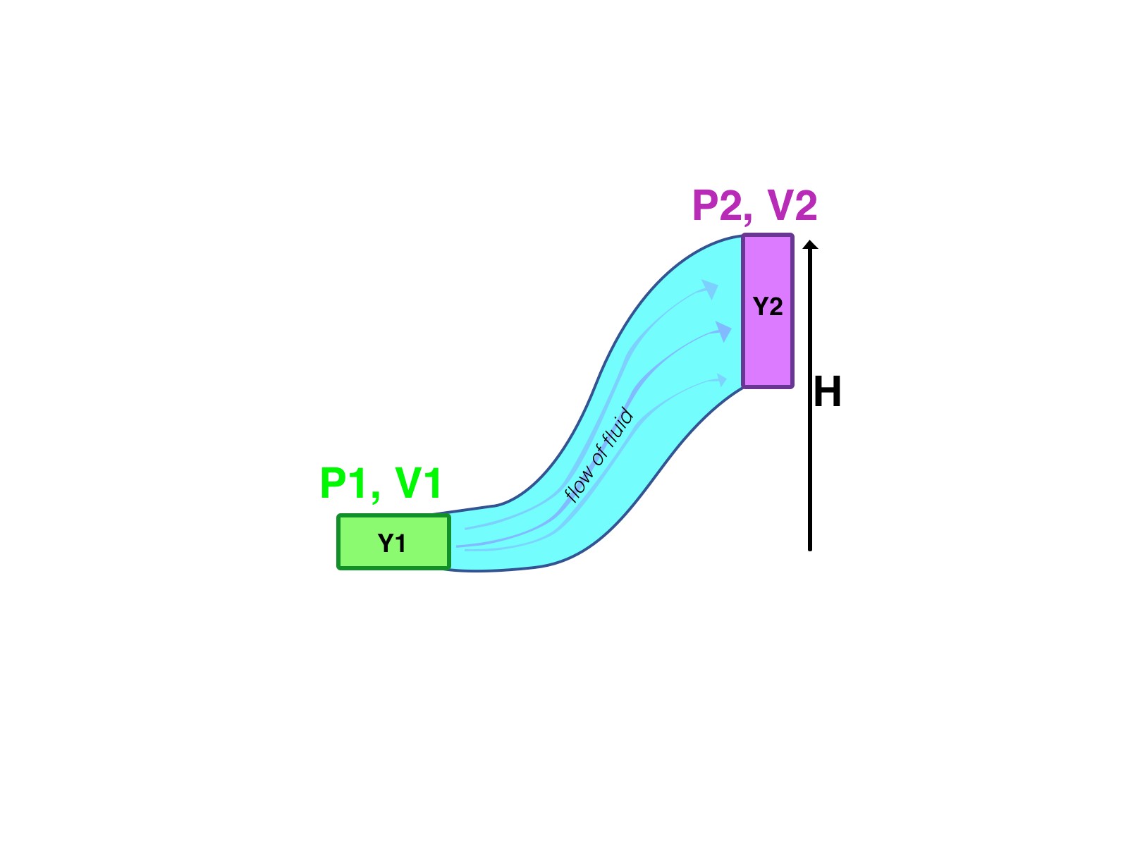
Bernoulli’s equation expresses conservation of mechanical energy per unit volume along a streamline for steady incompressible flow with negligible viscous losses. Pressure work, kinetic energy per unit volume, and gravitational potential energy per unit volume contribute to the sum below.
The term ½ρv² is kinetic energy per unit volume, with units J/m³ = Pa. Here v is the fluid speed.
The term ρgH is gravitational potential energy per unit volume relative to a chosen height datum. The elevation difference between a large tank’s surface and its outlet can drive efflux.
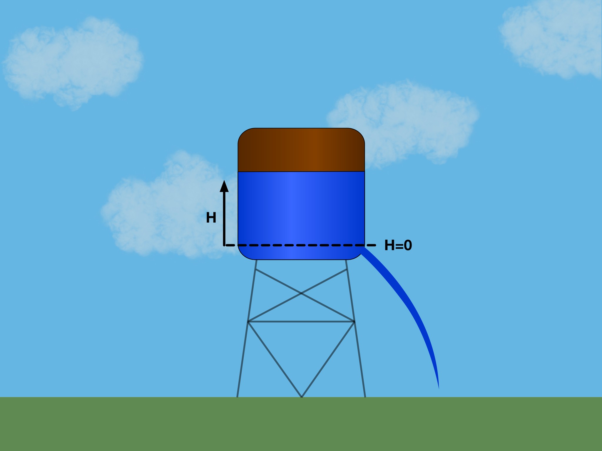
Imagine that a hole was created in the bottom of a wooden cylindrical vessel due to the wood rotting over time as shown below. At this point, the water starts to pour out of this hole. Knowing that there is a hole with distance from the the top of the water level and that the vessel is open to the air, find the velocity exiting the hole .
Example Problem 8.2.2
Step 1: Set up your Bernoulli Equation
It should make sense that we are using Bernoulli’s equation because this is a fluid with varying heights, pressures and velocities. Let’s use Bernoulli’s Equation:
Here the left side of the equation represents the top of the tank, while the right hand side represents the bottom of the tank where the hole is.
Step 2: Realize that the pressures are equal
How is that? Well in the problem statement, it was specified that the water was exposed to the open air, meaning that the pressure at the top is atmospheric pressure. The water coming out from the hole is also exposed to atmospheric pressure, therefore the pressures at both
points are the same. To make our lives easier let’s make the claim:
Meaning that we can simplify the Bernoulli equation to just:
Step 3: Eliminate variables
We can clean this equation up even more to make it simpler. Since the pressures are equal, those will cancel out. Also since we set our datum to be at where the hole is, the height at that point is . So we can now write our equation as:
continuity to help you estimate certain values and make educated guesses.
Solving for gives us:
The initial cross-sectional area of the vessel at
Which can be cleaned up to make it look like:
And by canceling out the densities, we get:
Step 4: Solve for the final velocity
We can solve for to get:
So this is our final equation.......SIKE. We can actually simplify this even further. How?
Step 5: Use concept of continuity to help simplify
What do we mean ? Use the equation of
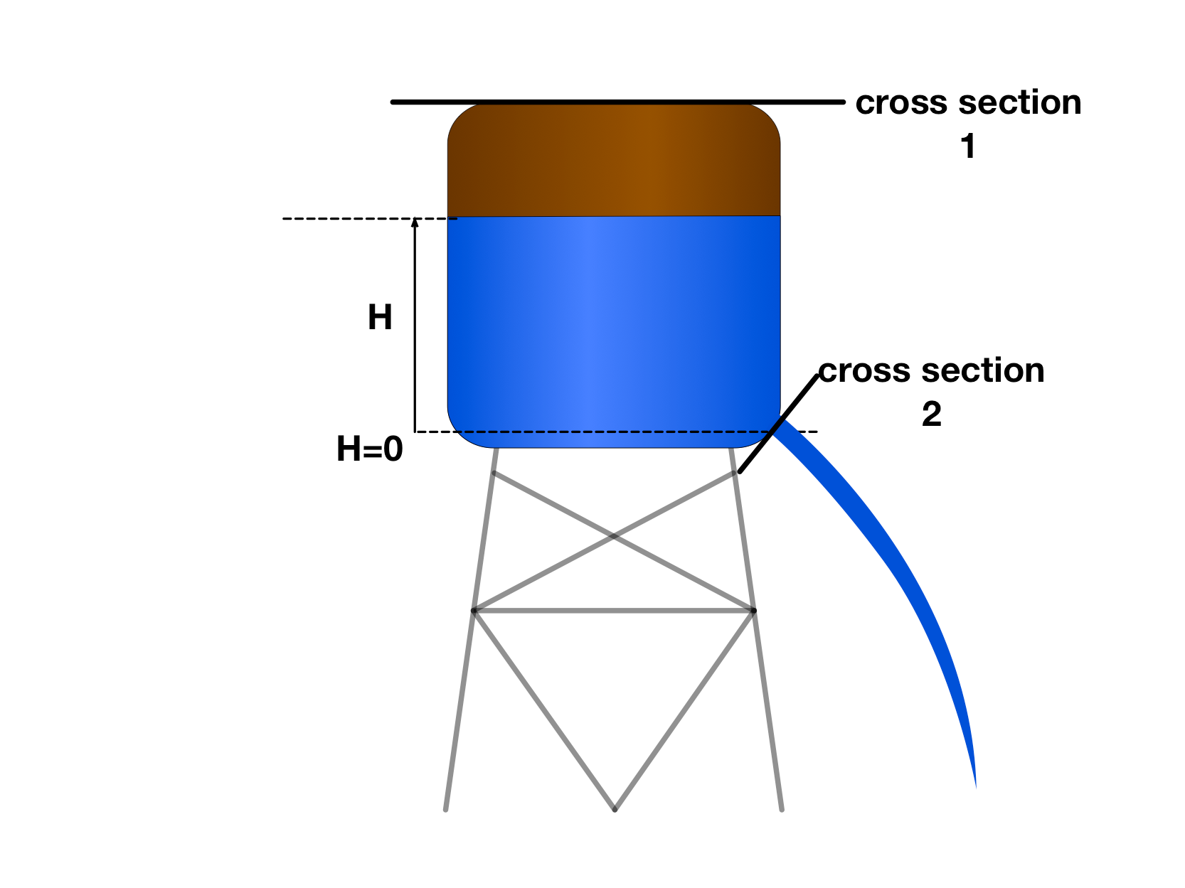
Here are the cross sections of the tank that we’re going to look at.
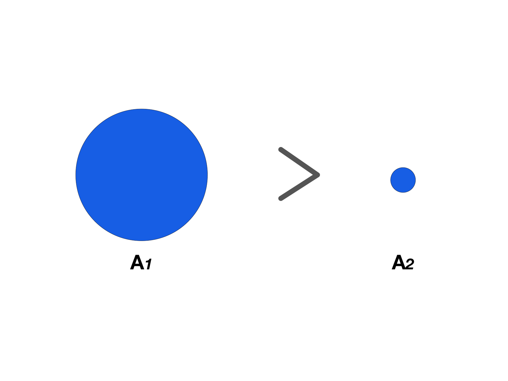
the top of the tank is much larger than the hole that’s created at the bottom. Meaning that:
If the area at the top is much larger with respect to the area of the hole, the final velocity will be much larger than the initial velocity. So if holds to be true, then we can make another statement:
Neglect the free-surface speed only if the tank surface area is much larger than the opening area, A₁ ≫ A₂. Then v₁/v₂ = A₂/A₁ ≪ 1, and the outlet speed is approximately √(2gH₁).
Pop Quiz 8.2.1 Continuity and Bernoulli’s Principle
Question 1 of 5 · 0 correct
AP Topic 8.4 · Read the worked solution
A fluid flows through the inlet of a pipe with diameter and velocity . The fluid exits at the outlet of the pipe which has a diameter of . What is the velocity at this point?
Read every full question without answers
Question 1
Question 2
Question 3
Question 4
For steady incompressible flow through the pictured sections, rank the mean speeds from greatest to least (I–IV).
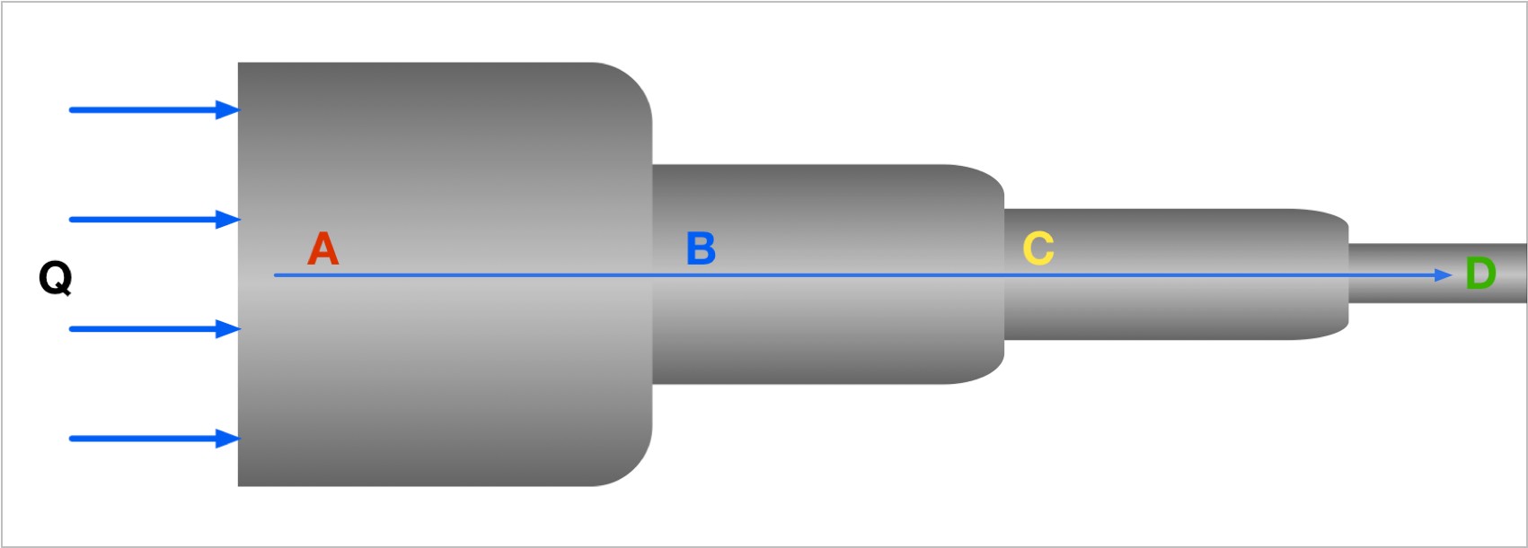 1234
Match these labels to the numbered figure targets. Write your matches before opening the separate worked answer.
Question 5
Assume the pictured pipe is horizontal and the flow is steady, incompressible, and lossless. Rank the static pressures from greatest to least (I–IV).
1234Match these labels to the numbered figure targets. Write your matches before opening the separate worked answer.


Reviewed physics notes (15)
These corrections keep the original lesson’s purpose while fixing errors in the source edition.
- Products Av use normal speed, not an unconstrained vector velocity. — Reference 1
- Clarifies that steady flow can have convective acceleration and that a constant-acceleration taper is an idealization. — Reference 1
- Bernoulli is an energy balance, whereas continuity is mass conservation; they are not the same principle. — Reference 1
- The term is energy density rather than the whole fluid’s kinetic energy. — Reference 1
- Clarifies scalar energy density and height datum. — Reference 1
- The numerical substitution mistakenly squares the diameter ratio instead of raising it to the fourth power. — Reference 1
- Corrects the inlet speed; the original 2.8 m/s does not satisfy both continuity and constant-acceleration kinematics. — Reference 1
- The source says the final area is larger even though diameter halves. — Reference 1
- Area depends on the square of diameter. — Reference 1
- Corrects outlet speed and verifies both governing equations. — Reference 1
- A mere inequality A₁ > A₂ does not justify neglecting v₁; the area ratio must be small. — Reference 1
- An area ratio is dimensionless; the source incorrectly attaches m² to ratio choices. — Reference 1
- The marked decrease relies on Bernoulli’s assumptions. — Reference 1
- Makes the continuity assumptions explicit for the image ranking. — Reference 1
- Pressure cannot be ranked from area alone if elevation or head losses differ. — Reference 1
Glossary and deeper reading · 7 refreshers
These editorial refreshers supplement the reading. Definitions and examples are added guidance; original source wording and recorded answers remain in their original context.
-
Fluid
A fluid is a material that flows and continuously deforms under a sustained shear stress. Liquids and gases are both fluids, although their compressibility and other properties can differ greatly. For example, both water in a pipe and air flowing through a duct are fluids.
-
Velocity
Velocity describes how position changes with time and includes direction. Instantaneous velocity describes one moment, while average velocity is displacement divided by elapsed time. For example, a car turning a corner can change velocity while maintaining the same speed.
-
Incompressible fluid
An incompressible-fluid model treats density as constant despite pressure changes in the modeled situation. This approximation often works for liquids over modest pressure ranges but is not a universal property of all fluids. For example, water flowing through a narrowing pipe can often be treated as incompressible.
-
Mechanical energy
Mechanical energy is the sum of the kinetic and potential energies included in a model. It stays constant when transfers to or from other energy stores and across the chosen boundary are absent. For example, a pendulum’s mechanical energy can remain approximately constant while energy shifts between motion and gravitational configuration.
-
Streamline
A streamline is a curve tangent to the local fluid velocity at each point at one instant. In steady flow its shape stays fixed and fluid particles follow it, while in changing flow a streamline need not be a particle’s full path. For example, streamline arrows around a smooth obstacle show the local direction of the passing fluid.
-
Kinetic energy
Kinetic energy is energy associated with motion relative to a chosen reference frame. For a nonrelativistic translating object it is one half of its mass times speed squared. For example, doubling a cart’s speed quadruples its translational kinetic energy when its mass stays fixed.
-
Gravitational potential energy
Gravitational potential energy is energy associated with the relative positions of attracting masses. Near Earth, changes can be approximated by mass times gravitational field strength times height change when that field is nearly constant. For example, lifting a book increases the gravitational potential energy of the book–Earth system.