Capacitors
Original source retained for reference; this draft does not establish AP coverage.
Original author draft. Original wording and recorded answer states are preserved without claiming reviewed scientific correctness or AP alignment.
Physics 2 original textbook · Chapter 3
Section 2
Section 2
A capacitor consists of two conductors separated by insulation. In the usual initially neutral two-terminal setup, a voltage supply transfers charge from one conductor to the other, establishing equal and opposite net charges +Q and −Q. Induction alone does not guarantee that two isolated conductors acquire opposite net charge.
When talking about capacitors one often discusses the idea of capacitance. It is a quantity defined by the equation
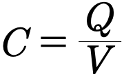
Where Q is the charge given to the first conductor of the capacitor and V the voltage or potential difference between the plates. The capacitance is a constant value for a conductor due to the fact that the voltage across a capacitor is proportional to the charge Q that is put into the capacitor.
The capacitance is given the unit of a farad which is commonly denoted by the letter F and as capacitances definition suggests the farad is equivalent to 1 coulomb per volt.
Although many types of geometries exist for capacitors one which is fairly easy to study may be formed by placing two parallel plates a small distance d apart. This is called a parallel-plate capacitor.
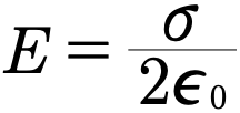
Let’s calculate the capacitance for parallel-plate capacitor. The piece of information we will need is the voltage between the plates when they are a a charge Q. If we are close to a plate we may approximate the electric field as the field of an infinite plate
Interactive 1.2 The Parallel-plate Capacitor
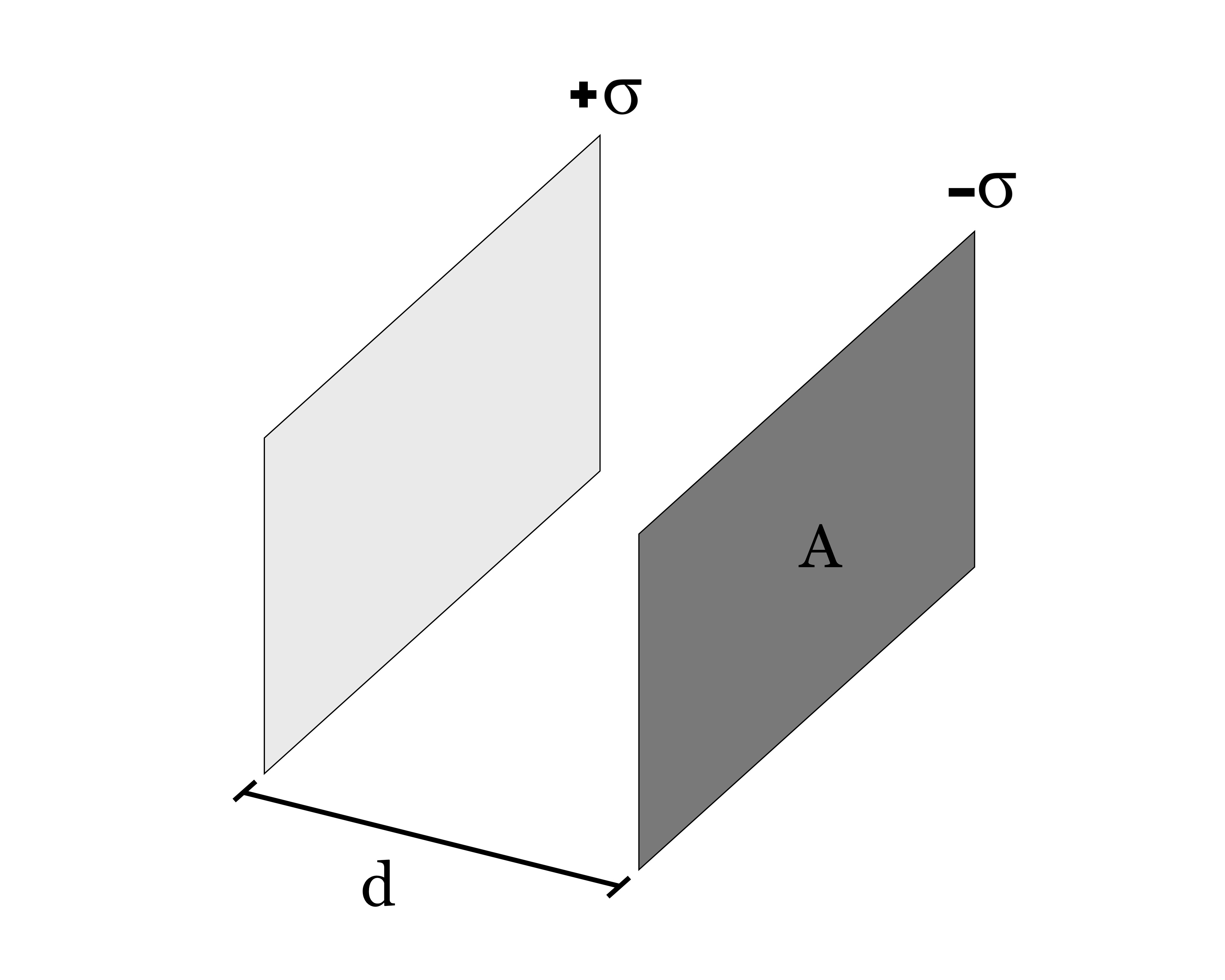
Area of Plates
Each plate is given the same total area and are placed parallel to one another so that their centers match.
Separation
The plates are separated by a distance d.
Charged Plated
For an initially neutral two-terminal capacitor, the connected supply transfers equal and opposite charges between the conductors. Their surface charges adjust to make each conductor equipotential. Induction redistributes charge but does not create the opposite net charge on an isolated plate.
Archived original widget · contains the source error
Each plate is given the same total area and are placed parallel to one another so that their centers match.
The plates are separated by a distance d.
Since the plates are conductors as one plate becomes charged and creates an electric field the other plate becomes oppositely charged.
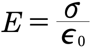
The voltage across the plates is given by
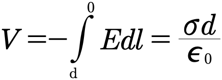
Note that when doing these problems start your integral at the negative plate and move to the positive plate. This ensures that you get the correct sign.
Finally for a plate of area A with a charge distribution σ it’s charge is given by
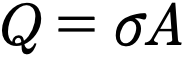
Therefore
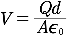
And finally we get an expression for the capacitance
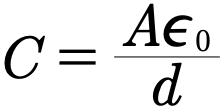
What is important here is that the capacitance of the capacitor is completely independent of the charge so that the maximum capacitance is completely determined by the geometry of the capacitor.
Example 3.2.1
Optional coaxial-cylinder capacitance method. Prerequisites: cylindrical Gauss’s law, a radial potential integral and logarithms. This extends the parallel-plate calculation model. This preserved source example makes no AP coverage claim.
Find capacitance of long coaxial conducting cylinders of length L, radii a<b.
Authored clarification: Vacuum; negligible end effects; charges ±Q.
In this problem we have to coaxial sheets placed inside one another and we are asked to determine the capacitance. Solving for the capacitance requires us to really do only a single thing. Determine the voltage between the plates.
To determine the voltage of this setup we will first need to determine the electrical field between the plates. The easiest way to determine the electrical field of this setup is to use Gauss’s law since there is a large degree of symmetry and the distance between the sheets will be so small compared to their length they could be considered practically infinite.
By Gauss’s Law we have that
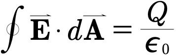
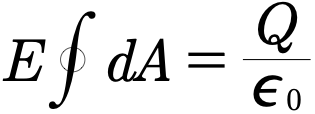
Between long coaxial conducting cylinders, the electric field is radial. It is perpendicular to the curved Gaussian surface and parallel to its outward normal, with zero flux through the end caps. With negligible end effects, .
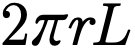
The surface area of a cylinder of radius r and length L is given by
Substituting in the surface area for the integral and and then solving for E reveals that
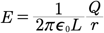
The voltage between the two plates is then given by the integral for potential difference
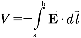
If we move along a radius from the smaller sheet to the larger sheet we get that
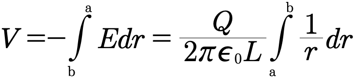
Doing the proper integration yields the result that
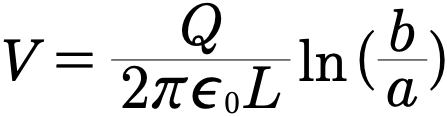
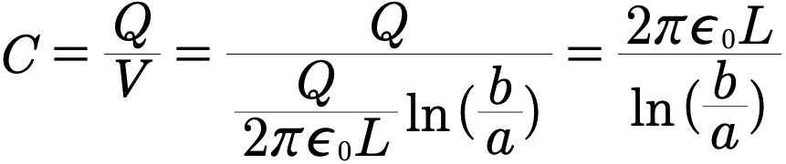
Finally substituting V into the our definition of the capacitance yields the desired answer
Interactive 1.3 Cylindrical Capacitor
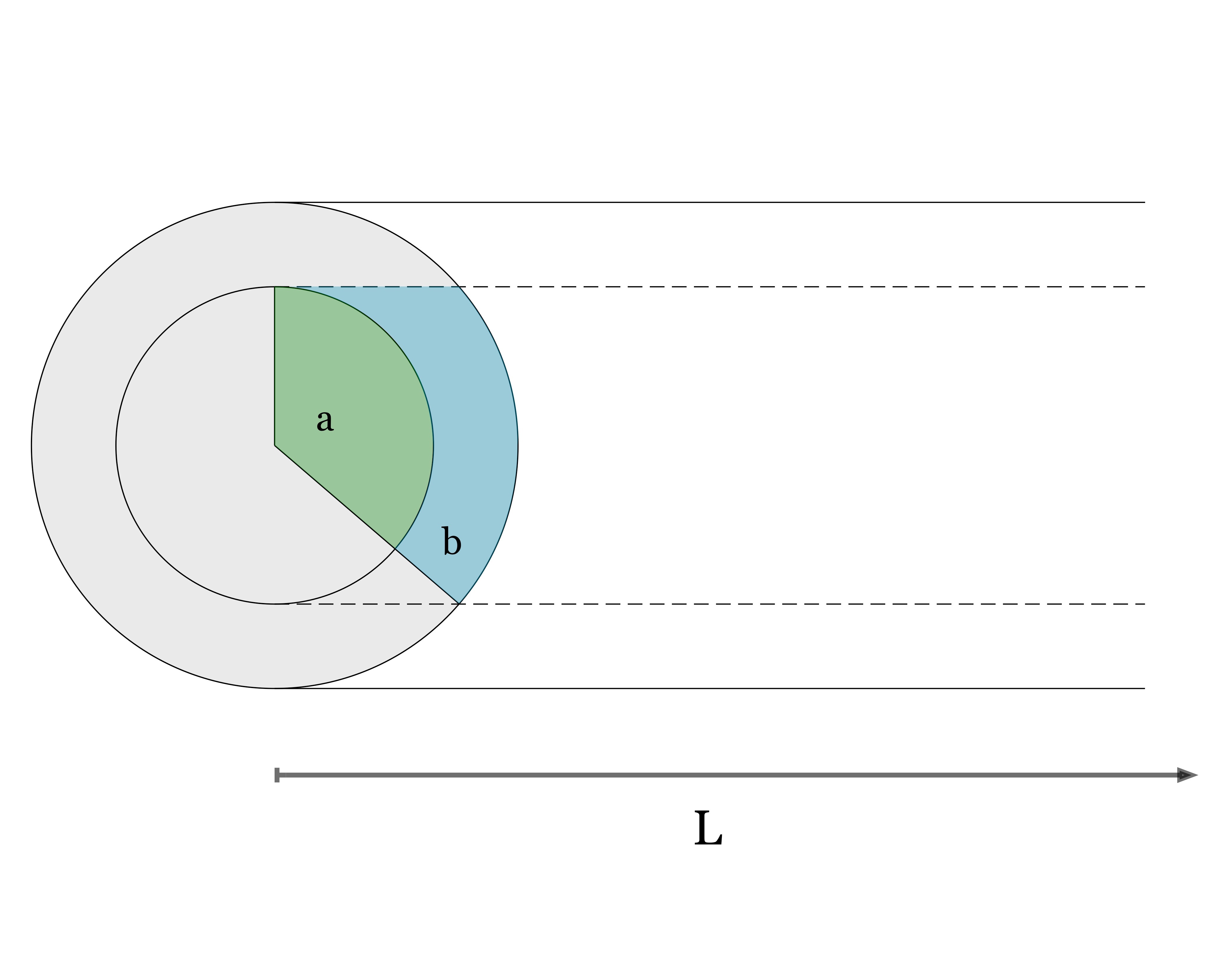
The Outer Cylinder
The outer cylinder has a radius of b and is represented by the solid line.
The Inner Cylinder
The inner the cylinder has a radius of a and is represented by the dotted line.
Example 3.2.2
Optional concentric-sphere capacitance method. Prerequisites: a radial field and potential integral. This extends the parallel-plate calculation model. This preserved source example makes no AP coverage claim.
Find capacitance of concentric conducting spheres of radii a<b.
Authored clarification: Vacuum, opposite charges ±Q.
This example is similar to example 3.2.1 where we found the capacitance of two coaxial cylindrical conducting sheets. We must do the same thing, determine V.
The electric field between the two spheres can be found by considering Gauss’s Law. The electric field is found to be
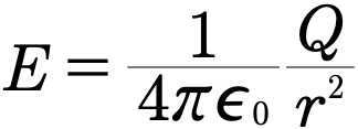
If the inner surface is positively charged then the integral for the voltage reads
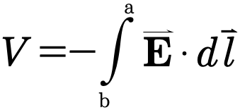
Substituting in our values then leaves us with

Finally, using the definition of capacitance we have that

Review 1.2 Capacitors and Capacitance
This review preserves the author’s recorded prompts, choices, and answer states. Corrected items have separate reviewed explanations and keys; unchanged draft keys are marked unreviewed. Unfinished items are not scored.
Original question 1
A two-terminal capacitor has its negative plate chosen as V=0. If its positive plate is at potential difference ΔV>0, what is that plate’s potential?
+ΔV
0
An absolute reference-independent value
Reviewed answer and reasoning
A
Only potential differences are intrinsic to the two-terminal description; the stated reference sets the plate potentials.
This reviewed version states the assumptions or convention needed for one determinate answer. The archived source prompt and key are retained.
Archived original question and recorded key · contains the source error
When determining the voltage across a capacitor it is customary do so so starting with the negative plate.
True
False
Original recorded key: A
Original question 2
For an ideal linear capacitor with fixed geometry and dielectric, does C depend on its stored free charge Q?
No
Yes
Reviewed answer and reasoning
A
C=Q/ΔV is constant in the linear model. Nonlinear dielectric behavior or breakdown lies outside these conditions.
This reviewed version states the assumptions or convention needed for one determinate answer. The archived source prompt and key are retained.
Archived original question and recorded key · contains the source error
Capacitance does not depend on the charge placed into a capacitor.
True
False
Original recorded key: A
Original question 3
For what dimensions will a parallel-plate capacitor have the most capacitance?
A = 1 cm², d = 2 mm
A = 1 cm², d = 1 mm
A = 2 cm², d = 2 mm
A = 2 cm², d = 1 mm
There is more than one highest
Reviewed answer and reasoning
D
C proportional A/d; greatest given ratio is 2 cm^2 / 1 mm.
The independent semantic audit confirms this source prompt and recorded key under its stated conditions.
Archived original question and recorded key · contains the source error
For what dimensions will a parallel-plate capacitor have the most capacitance?
A = 1 cm², d = 2 mm
A = 1 cm², d = 1 mm
A = 2 cm², d = 2 mm
A = 2 cm², d = 1 mm
There is more than one highest
Original recorded key: D
Original question 4
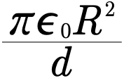
A parallel plate capacitor is fashioned from two disks of radius R a distance d apart. Express the capacitance of the setup in terms of R, d, and appropriate constants.
None of the above
Reviewed answer and reasoning
A
Neglect fringing, C=epsilon0 pi R^2/d for two circular plates.
The independent semantic audit confirms this source prompt and recorded key under its stated conditions.
Archived original question and recorded key · contains the source error
A parallel plate capacitor is fashioned from two disks of radius R a distance d apart. Express the capacitance of the setup in terms of R, d, and appropriate constants.
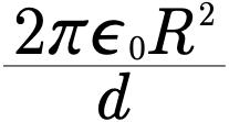
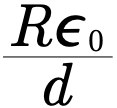
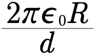
None of the above
Original recorded key: A
Original question 5
A capacitor has a capacitance of 500 mf and has a charge of 5 coulomb placed on it. What is the voltage across the capacitor?
10 mV
100 mV
10 V
100 V
None of the above
Reviewed answer and reasoning
C
Q=CV=.500 F*10 V=5 C; standard unit notation is mF.
The independent semantic audit confirms this source prompt and recorded key under its stated conditions.
Archived original question and recorded key · contains the source error
A capacitor has a capacitance of 500 mf and has a charge of 5 coulomb placed on it. What is the voltage across the capacitor?
10 mV
100 mV
10 V
100 V
None of the above
Original recorded key: C
Reviewed worked examples
These authored derivations are paired with the original example identities. Added assumptions are stated.
Optional coaxial-cylinder capacitance method. Prerequisites: cylindrical Gauss’s law, a radial potential integral and logarithms. This extends the parallel-plate calculation model. This preserved source example makes no AP coverage claim.
Example 3.2.1 · reviewed solution
Find capacitance of long coaxial conducting cylinders of length L, radii a<b.
Authored clarification: Vacuum; negligible end effects; charges ±Q.
Use a finite coaxial Gaussian cylinder.
Integrate radial field.
Use C=Q/ΔV.
Check
As b approaches a, capacitance grows.
Optional concentric-sphere capacitance method. Prerequisites: a radial field and potential integral. This extends the parallel-plate calculation model. This preserved source example makes no AP coverage claim.
Example 3.2.2 · reviewed solution
Find capacitance of concentric conducting spheres of radii a<b.
Authored clarification: Vacuum, opposite charges ±Q.
The field between spheres is radial.
Integrate from a to b.
Divide Q by ΔV.
Check
As b→∞, C→4πε₀a for an isolated sphere.
Glossary and deeper reading · 6 refreshers
These editorial refreshers supplement the reading. Definitions and examples are added guidance; original source wording and recorded answers remain in their original context.
-
Capacitor
A capacitor stores energy by separating charge between conducting regions. In the ideal two-plate model, opposite plate charges create a potential difference related to charge by the capacitance. For example, disconnecting a charged capacitor from a battery leaves energy stored until a discharge path is provided.
-
Electrical conductor
An electrical conductor contains charge carriers that can move through the material. In electrostatic equilibrium, mobile charges redistribute until the electric field within the conducting material is zero. For example, excess charge on an isolated metal object resides on its surface after the charges settle.
-
Potential difference
Potential difference is the change in electric potential between two locations. It represents electric potential-energy change per unit charge and is measured in volts. For example, the potential difference across a resistor describes the energy transferred per coulomb passing through it.
-
Capacitance
Capacitance is the plate-charge magnitude divided by the potential difference for an ideal capacitor. It is measured in farads and depends on geometry and the material between the conductors. For example, increasing the overlap area of ideal parallel plates increases their capacitance when separation and dielectric stay fixed.
-
Electric charge
Electric charge is a conserved property that determines electric interactions. It can be positive or negative and is measured in coulombs; ordinary net charges arise from an imbalance of charged particles. For example, transferring electrons between initially neutral objects leaves one negatively charged and the other positively charged.
-
Electric field
An electric field assigns the electric force per unit positive test charge to each location. The field is produced by the sources and is a vector, while the force on a negative charge points opposite the field. For example, the electric field between ideal parallel capacitor plates can accelerate an electron opposite the field arrows.