Current Carrying Wires in Magnetic Fields
Original source retained for reference; this draft does not establish AP coverage.
Original author draft. Original wording and recorded answer states are preserved without claiming reviewed scientific correctness or AP alignment.
Physics 2 original textbook · Chapter 5
The original text includes unresolved figure references such as “blah”. Those references are retained without inventing a figure association.
Section Overview
Section 3
Current Carrying Wires in Magnetic Fields
As we know from the discussion of charges in magnetic fields, a charge moving in a magnetic field will experience a force. Since currents are just the movement of a bunch of charges, it would make sense that a current carrying wire would also experience some type of force when placed inside a magnetic field, which is in fact true.
In order to really study these things, we need some type of equation that gives us the ability to calculate the force on wires in various situations. Luckily the relation which describes this force can relatively easily be derived.
Consider the force law for a single moving charge

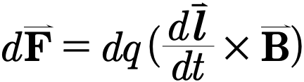
A small bit of that charge, dq, will experience a small bit of force, dF

If we let dl stand for a displacement in 3d space then for the velocity vector we can write that
Gallery 1.4 Currents in Magnetic Fields
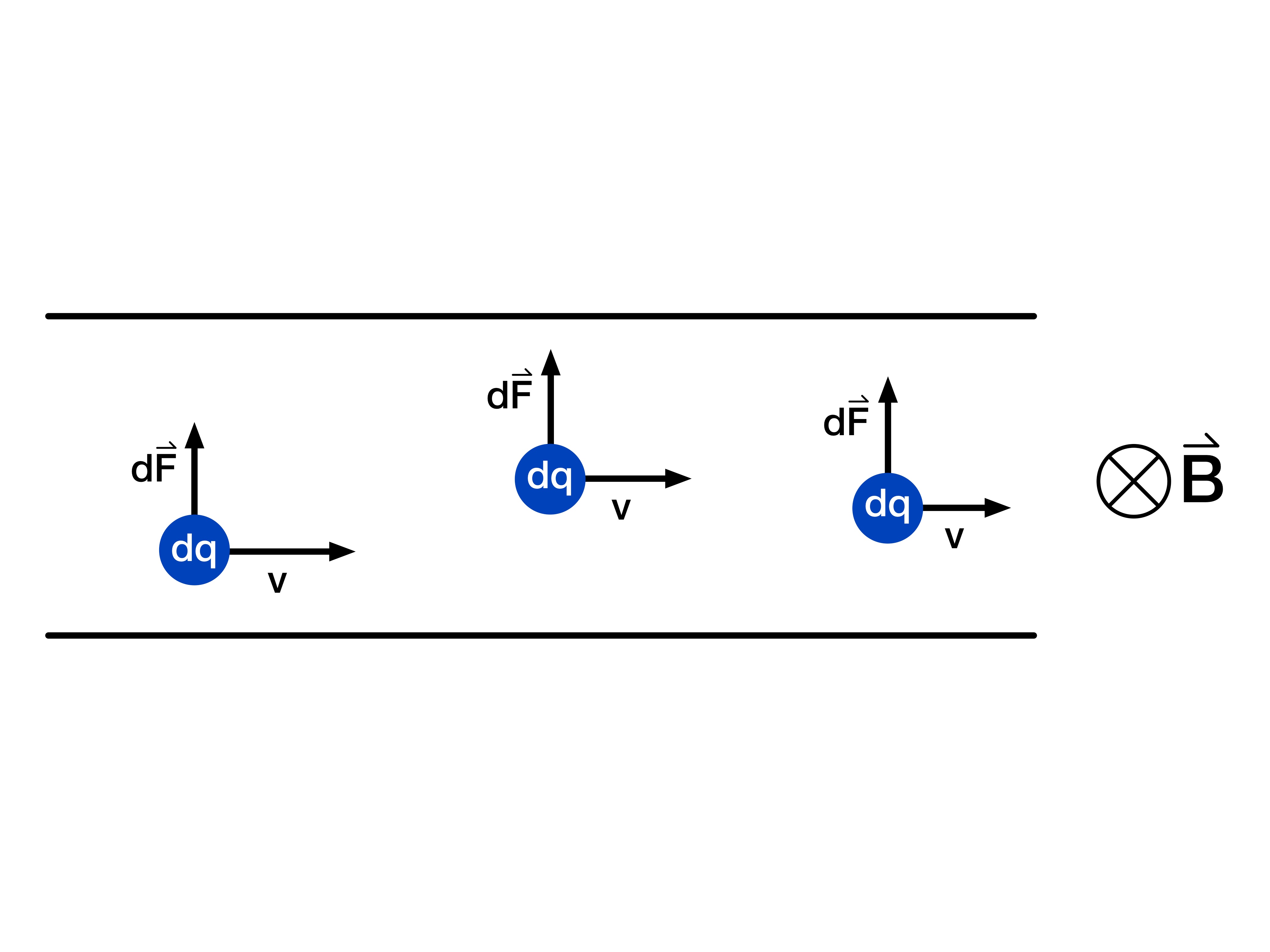
Currents, as we have discussed, are formed by many charges moving within a wire. In magnetic fields each of these charges experience a small amount of force, which then translates to a force acting on the wire.
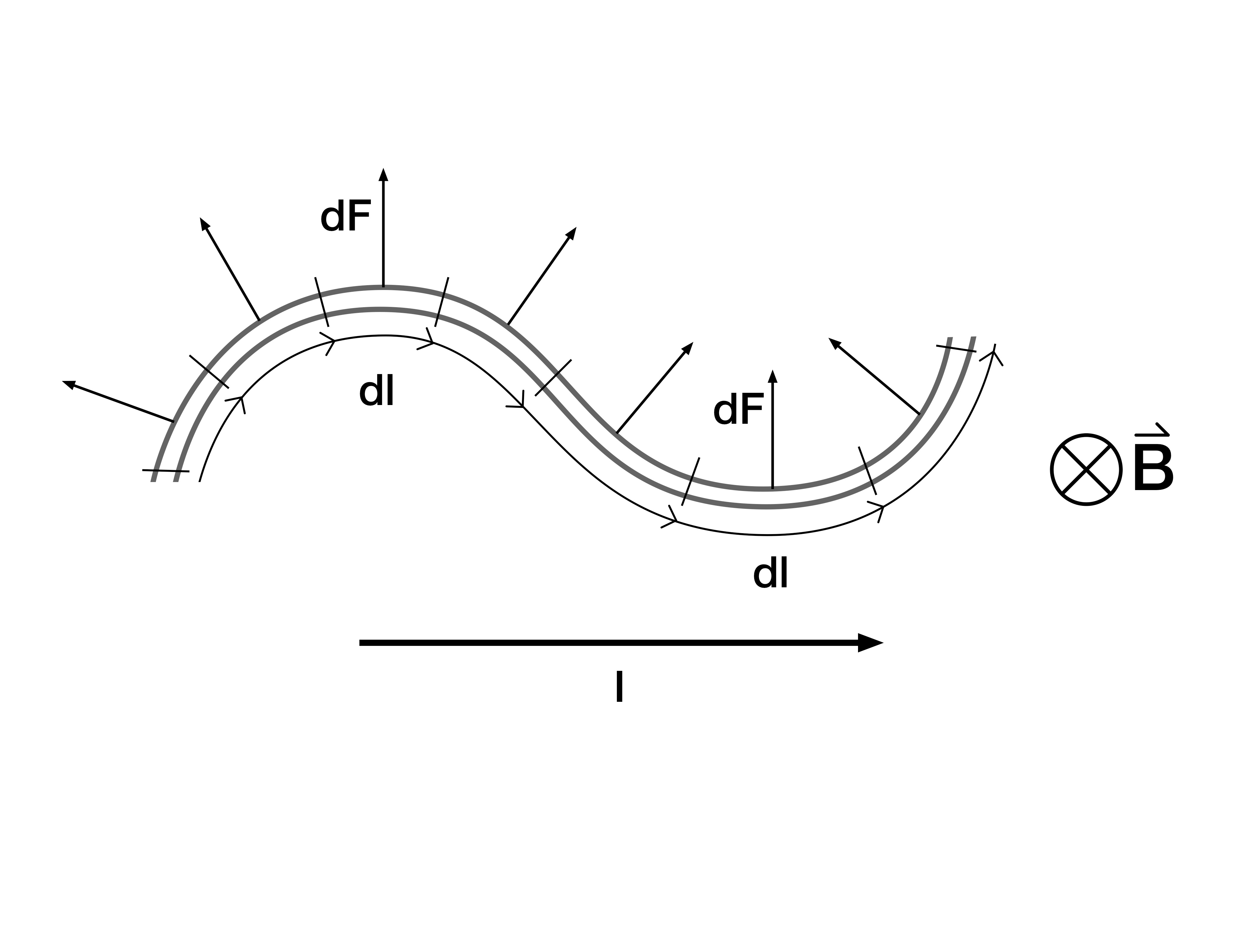
The force on the wire depends upon the direction of the flowing current since the force on the electrons depends upon the direction of their velocity. As a result to properly account for a curved wire we must note the direction which that current travels relative to the magnetic field.
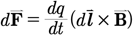
or

In the above equation, I stands for the magnitude of the current. Finally we can integrate over the equation to get
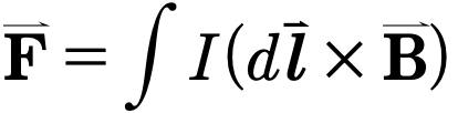
In order to calculate with this we must expand out the force law using the cross product.
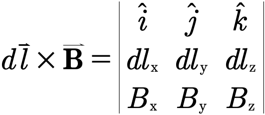
When this expression is integrated over, all that must be done is to match appropriate bounds and carefully consider the geometry of the shape you are integrating over.
Understanding the effects of a magnetic field on a straight wire is an extremely useful concept to have since it allows us to easily approximate forces on more complex systems. One key observation will be necessary for deriving the force on a straight wire. That is: since a straight wire has no bends in a uniform magnetic field, the force on any particular piece of wire will be the same.
Now let’s derive ourselves an equation for the magnitude of force on a straight wire in a uniform magnetic field
Consider the equations we stumbled upon while deriving the vector form of force on a current carrying wire.
If we wish to find the magnitude of such a force on some straight wire then we need to find the magnitude of the above equation.
Since both dl and B are uniform their magnitude only depends upon the angle between them so that we get

Plugging this back into our equation above we get that

Finally, if our wire is known to have a length L we can get that

Gallery 1.5 The Straight Line Current
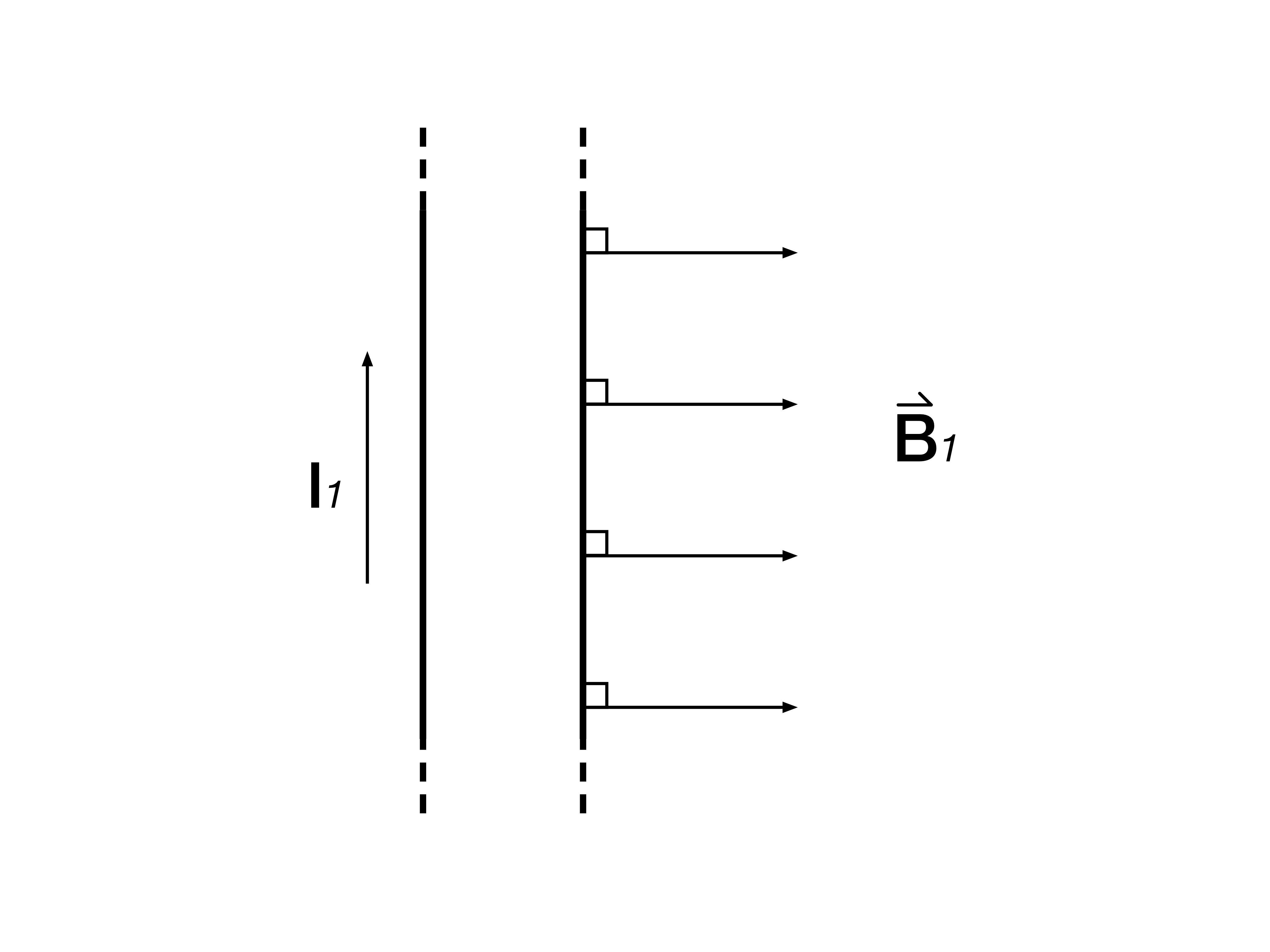
For a wire which is perpendicular to a uniform magnetic field the current the angle between the two need not be considered.
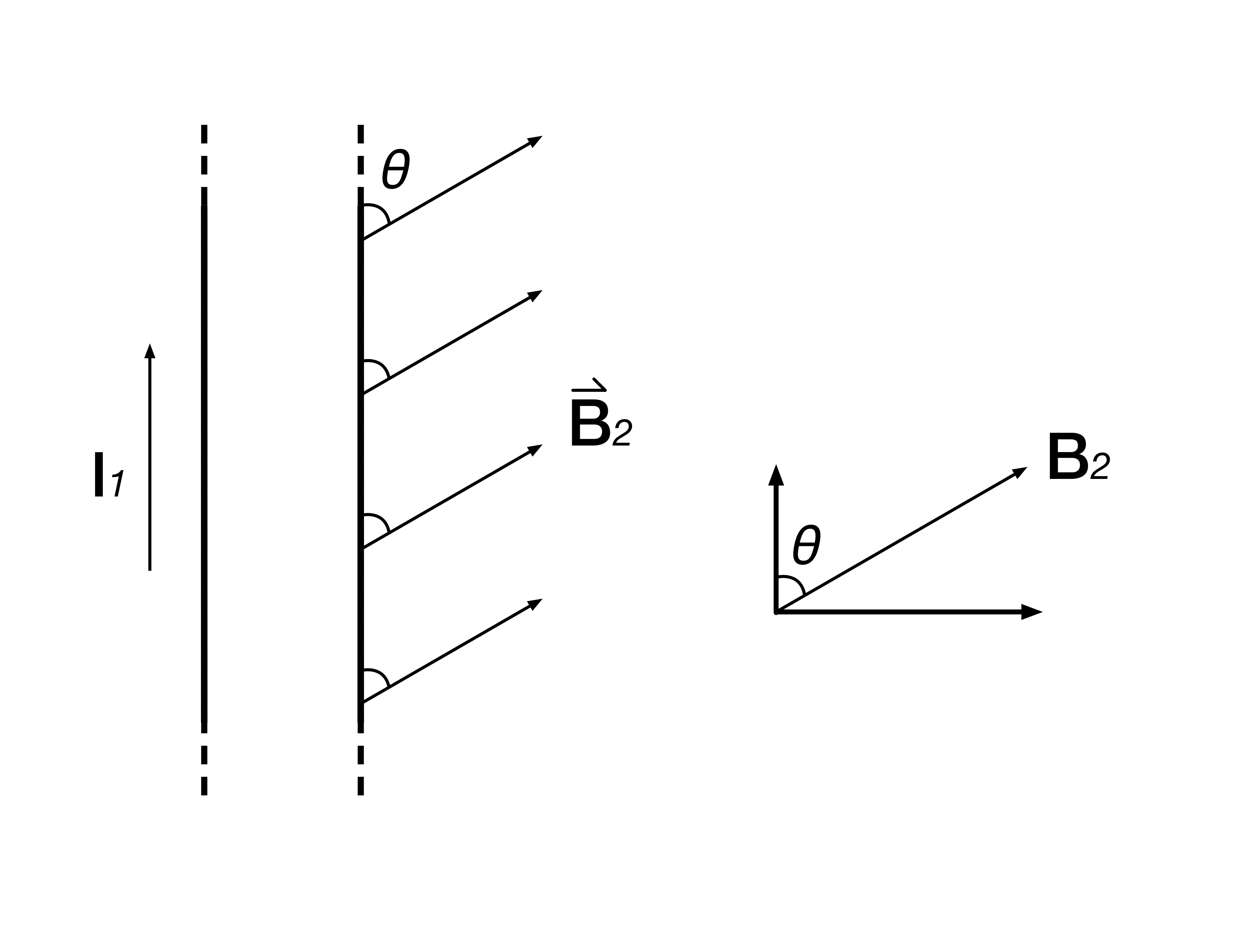
Once the the current and the magnetic field are not perpendicular the force on the wire changes are a result of the Lorentz Force Law.
Example 5.3.1
A rigid horizontal square loop, side 0.5 m, carries clockwise current 5 A in a static upward 2 T field. Find side forces and subsequent motion.
Authored clarification: Clockwise viewed from above; consider after switching transients.
The first portion of this problem asks us for the magnitude of the force on the sides of our square wire.
Using the equation derived for a straight line current we can do this without much of a problem. The only thing that we must notice is that since the wire rests on a horizontal surface and the magnetic field points directly upwards the current and magnetic field create a 90 degree angle.
The above now allows us to calculate the force using the given information. Therefore

Reviewed worked solution:
Each side is perpendicular to B.
Use the right-hand rule.
Each side force points inward toward the square’s center.
Sum force and torque.
Opposite sides cancel force; μ is antiparallel to B so torque is zero.
Answer: Each side experiences 5 N inward. A rigid loop has zero net force and torque in the stated static configuration.
Check: A flexible loop may deform; a general tilted loop may rotate despite zero net force.
Unfortunately straight wires are not the only current carrying media. In many cases it may be necessary to consider a wire which curves in some manner.
The simplest type of curved wire is likely to be the semi-circle. Consider a semicircle of current carrying wire of radius r and current I moving in the clockwise direction. If the wire is placed in a uniform magnetic field B what type of force would it experience? To determine this we again go back to the equations derived at the start of this section.
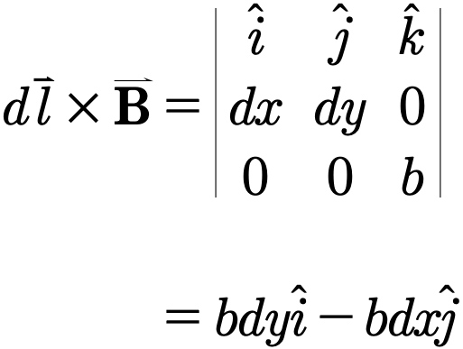
Let’s assume that the the magnetic field is perpendicular to the plane of the semi-circle so that B=(0, 0, b) and dl=(dx, dy, 0). The cross product of these two is then
Gallery 1.6 Curve Wires
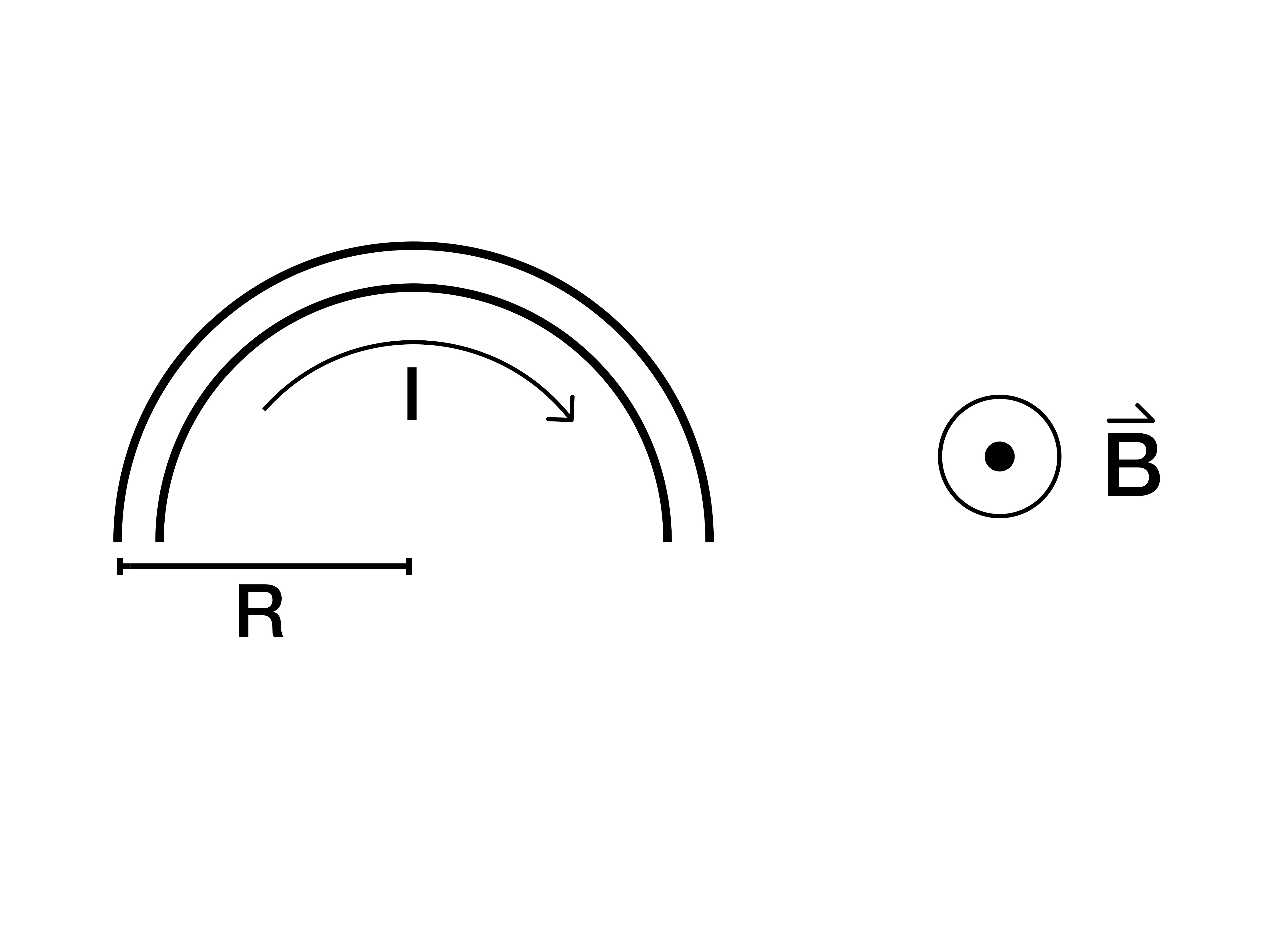
A wire rests on a table with a clockwise current with a uniform magnetic field pointing upwards (out of the page).
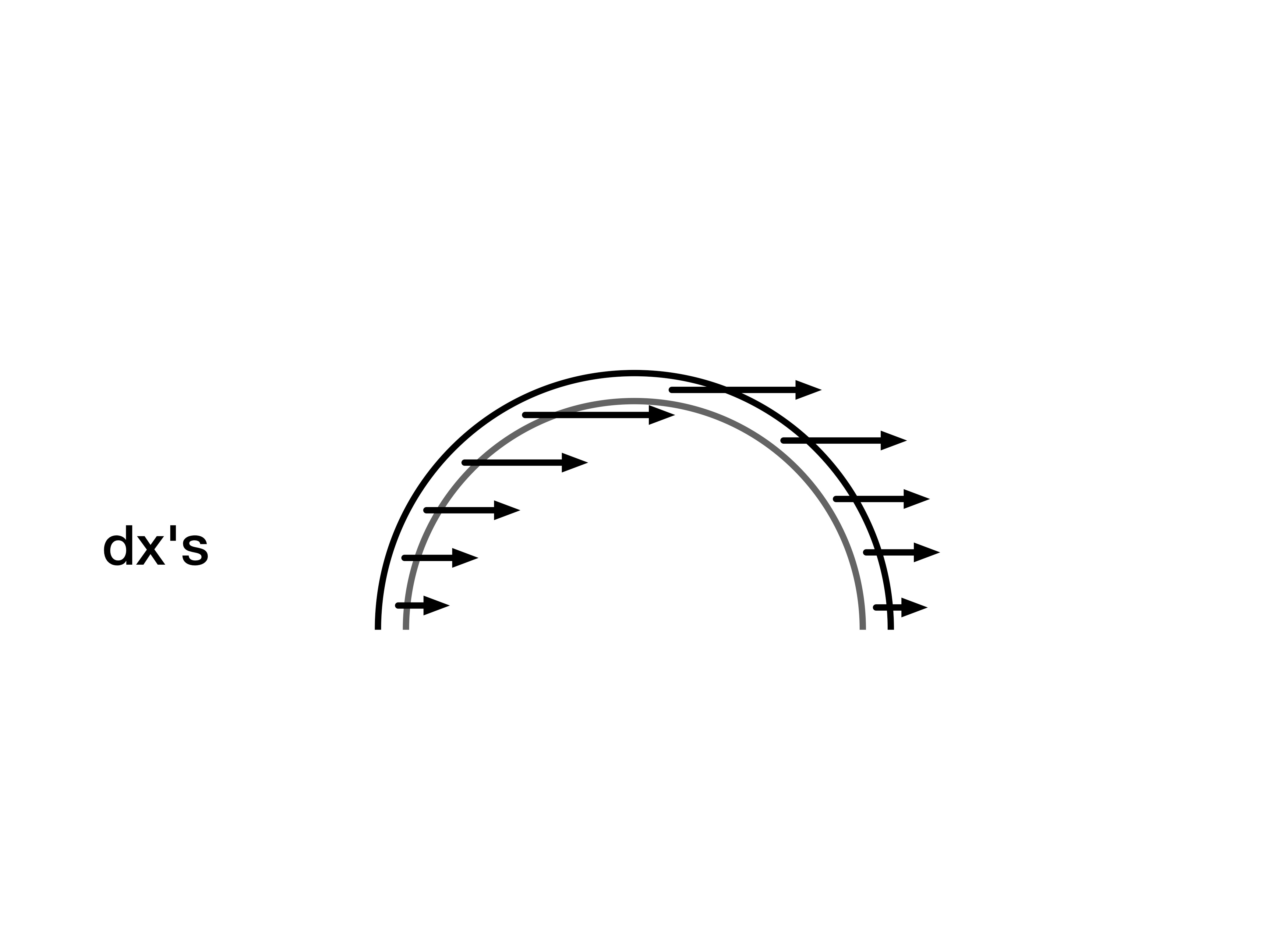
Each piece of length dl is composed of a dx and dy component. The dx components all point in the same direction so that they can be neatly added together.
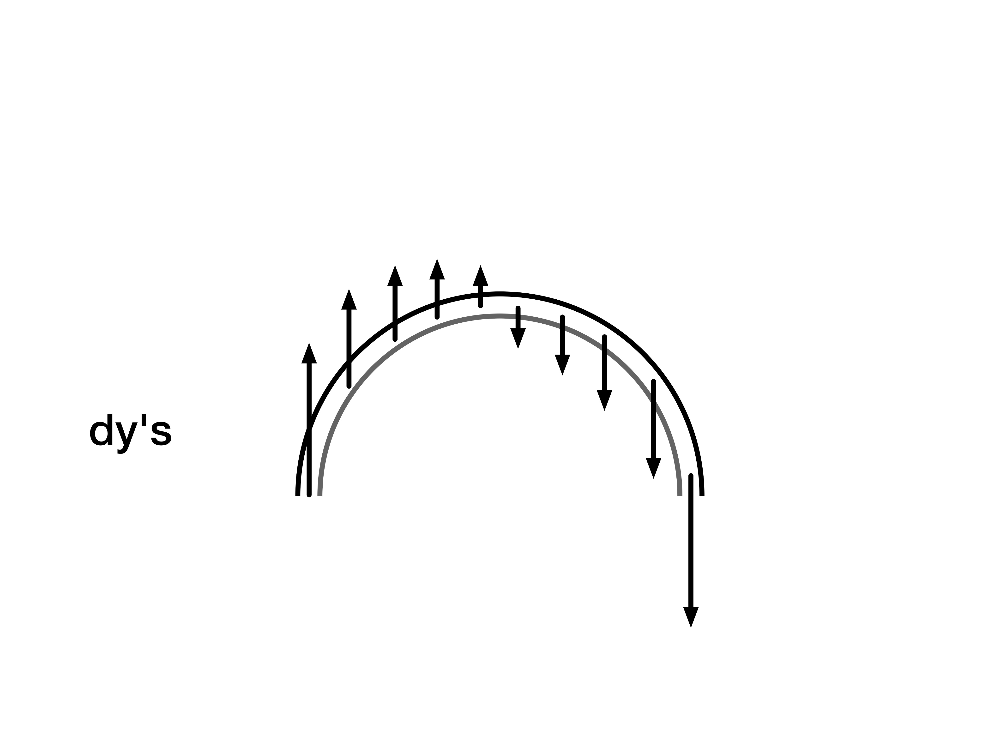
Unlike the dx components the dy components do not all point in the same direction. As a result they cancel each other out.

Next we look at the force in the y direction. Since here the current does not double over itself we simply have to integrate over the horizontal length of the wire, the diameter of the semi-circle.
Therefore the force exerted on the wire is given by

Example 5.3.2
Optional line-integral method. Prerequisites: vector integration along a curved wire. In a uniform field, the final force depends only on endpoint displacement. This preserved source example makes no AP coverage claim.
For the two-semicircle wire shown in Gallery5.3.4.1, find force in uniform B=Bŷ. Use the depicted current from left to right across total chord 4R.
Authored clarification: The archived caption says right-to-left and conflicts with the arrows; both directions are stated explicitly.
Reviewed worked solution:
Integrate the force along the current path.
Uniform B makes this an endpoint calculation.
Take the cross product.
Answer: for the depicted current; reversing current gives −4RIBẑ.
Check: Curvature does not change the endpoint formula in a uniform field.
Gallery 1.7 Example 5.3.2
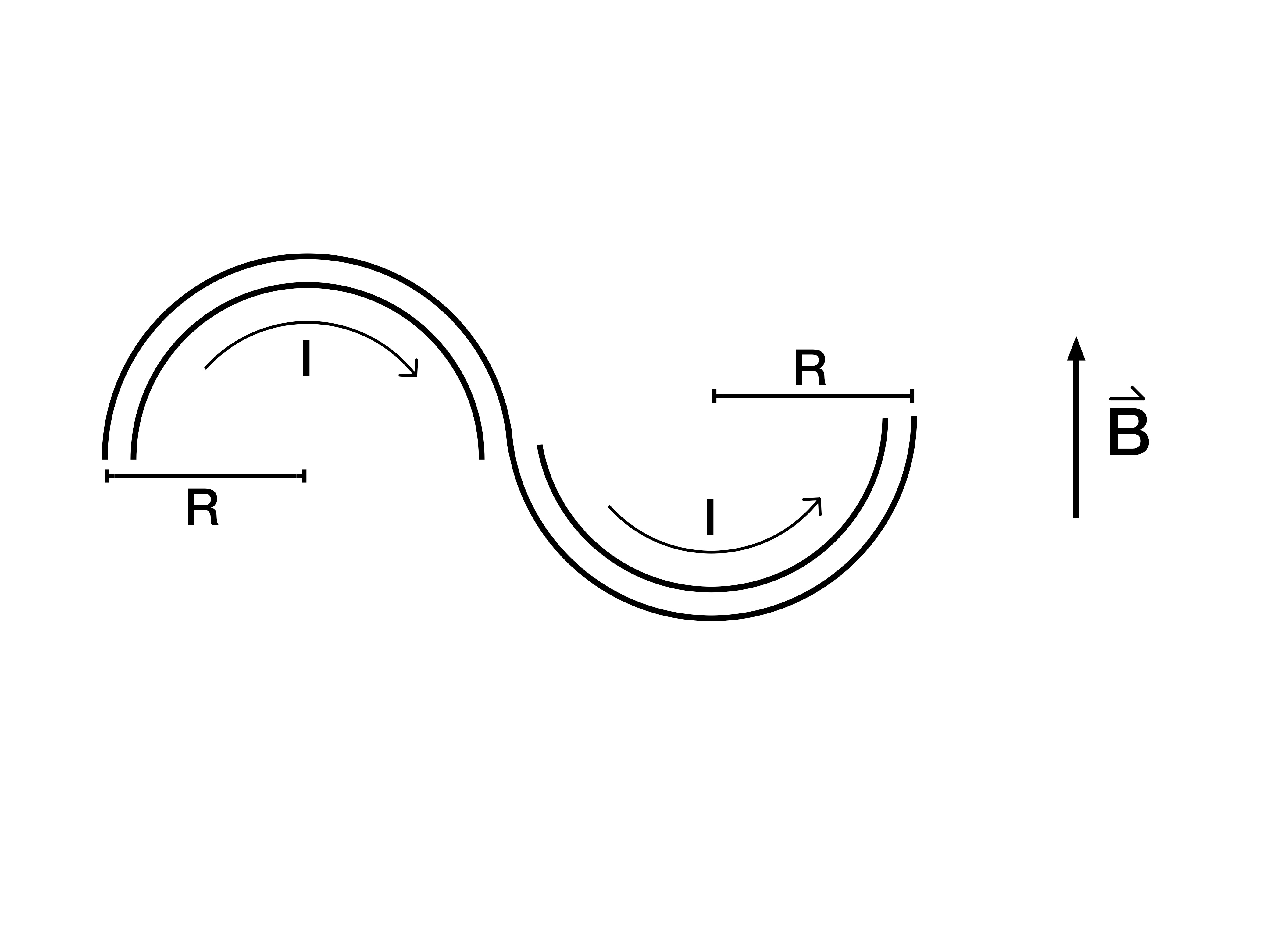
The original caption says right-to-left, while the arrows and worked path show left-to-right. For the depicted left-to-right current and uniform +y field, . Reversing current reverses this force; the archived caption records the conflict.
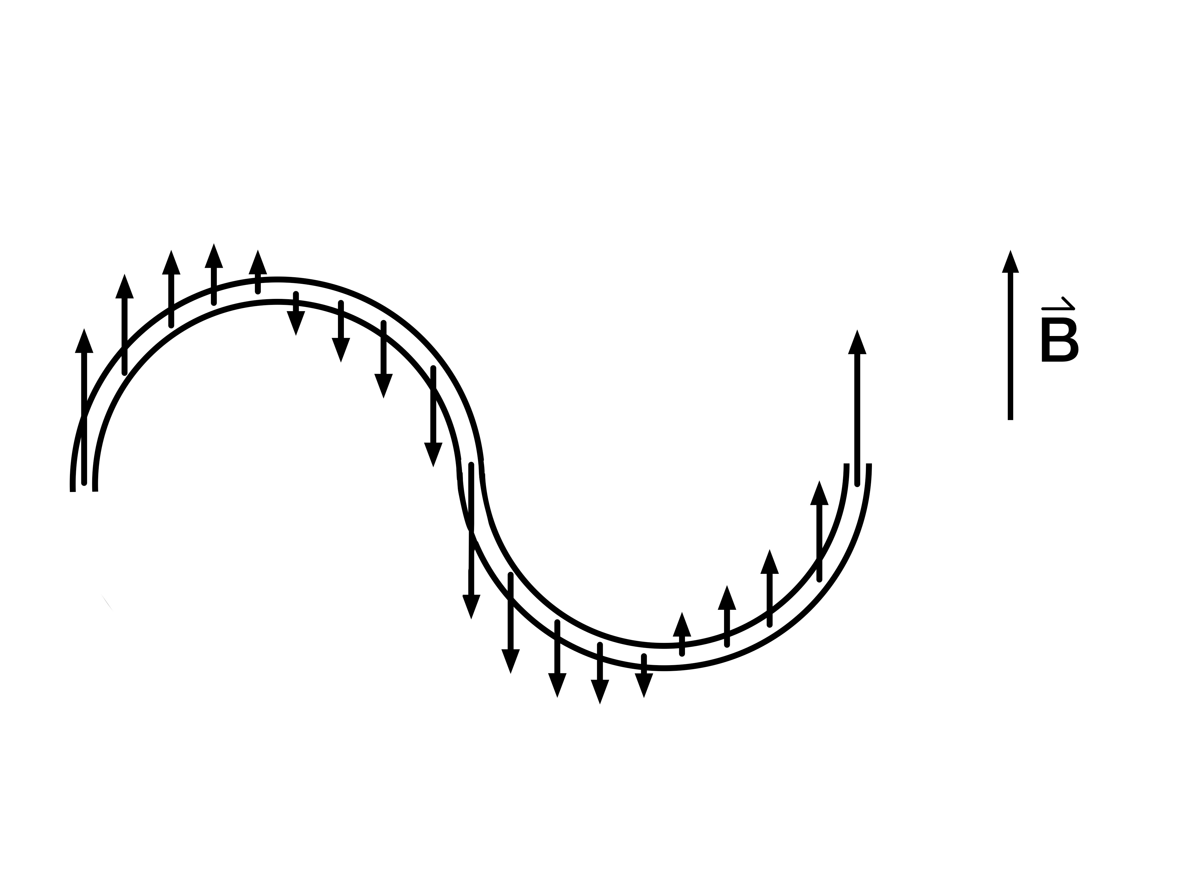
Since the dy components of dl are parallel to the magnetic field they contribute nothing to the force acting on the wire.
Archived original widget · contains the source error
Two semi-loops of wire with a current running from right to left are placed in a magnetic field as pictured.
Since the dy components of dl are parallel to the magnetic field they contribute nothing to the force acting on the wire.
Review 1.3 Magnetic Fields and Wires
This review preserves the author’s recorded prompts, choices, and answer states. Corrected items have separate reviewed explanations and keys; unchanged draft keys are marked unreviewed. Unfinished items are not scored.
Original question 1
A straight wire of length 2 m and current 5 A is laid along the x axis. If a magnetic field B = (0, 2 T, 3 T) is introduced what magnitude of force would you expect on the wire?
≈ 3 N
≈ 6 N
≈ 9 N
≈ 18 N
None of the above
Reviewed answer and reasoning
E
, magnitude .
Reviewed correction. Archived source choices and key remain readable.
Archived original question and recorded key · contains the source error
A straight wire of length 2 m and current 5 A is laid along the x axis. If a magnetic field B = (0, 2 T, 3 T) is introduced what magnitude of force would you expect on the wire?
≈ 3 N
≈ 6 N
≈ 9 N
≈ 18 N
None of the above
Original recorded key: A
Original question 2
Authored explicit geometry: a semicircular wire in the xz plane has radius 0.40 m, mass 0.40 kg, and current 30 A from its left endpoint to its right endpoint. Its horizontal chord is +x, and uniform B=1 T points +y. With g=9.8 m/s², what additional downward load can its upward magnetic force support?
20.08 N
24 N
3.92 N
0 N
Reviewed answer and reasoning
A
In uniform B, gives 2RIB=24 N upward. Subtract the wire’s weight 3.92 N. The original omits the required orientation; this is a stated replacement geometry.
Authored correction or explicit assumptions; this reviewed key is separate from the archived original recorded states.
Archived original question and recorded key · contains the source error
A half-circle of wire with current 30 A, mass 0.4 kg, and radius 40 cm is used to hang objects. If the ring is in a uniform B field of 1 T how much would the wire hold on earth?
≈ 2 N
≈ 5 N
≈ 10 N
≈ 20 N
None of the above
Original recorded key: D
Original question 3
Two equal-length parallel wire segments in the xy plane carry equal currents in opposite directions, are tied together, and are in a uniform external B=bẑ. What is the net force on the pair due to this external field?
0
IL|b|
2IL|b|
Reviewed answer and reasoning
A
Each segment experiences an opposite force of magnitude IL|b|. Their net external force is zero. Internal mutual forces can stress the tied assembly but do not alter its total force.
Authored correction or explicit assumptions; this reviewed key is separate from the archived original recorded states.
Archived original question and recorded key · contains the source error
Two wires are laid flat on the xy-plane and tied together so that they are parallel with their currents running opposite to one another. If the wires are placed in a region with a magnetic field of (0, 0, b) what magnitude of force would you expect the wires to experience.
LIB
2LIB
2πLIB
4IB
None of the above
Original recorded key: E
Original question 4
Authored explicit assumptions: a wire follows a 270° circular arc of radius R in the xy plane and carries current I in uniform B=bẑ. Find the force magnitude.
0
Reviewed answer and reasoning
A
In a uniform field, . The endpoint chord of a 270° arc is √2 R and is perpendicular to B. The original prompt omits R and I; they are explicitly supplied here.
This reviewed version states the assumptions or convention needed for one determinate answer. The archived source prompt and key are retained.
Archived original question and recorded key · contains the source error
A piece of wire is in the form of 3 quarters of a circle and is laid down flat on the xy-plane of some coordinate system. If the magnetic field in the region is defined by (0, 0, b) determine the magnitude of force on the wire.
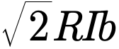
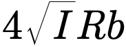
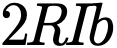
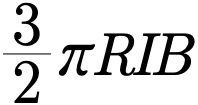
None of the above
Original recorded key: A
Original question 5
For b>0, a straight wire in B=bẑ experiences magnetic force in +x. If it lies along a coordinate axis in the xy plane, which current direction gives this force?
Along +y
Along −y
Along +x
Reviewed answer and reasoning
A
The cross product +ŷ×+ẑ=+x̂. A negative b would reverse the required current direction, so b>0 is stated.
This reviewed version states the assumptions or convention needed for one determinate answer. The archived source prompt and key are retained.
Archived original question and recorded key · contains the source error
A wire is placed in a magnetic field of the form (0, 0, b) and once let go began to be pushed in the positive x direction. If the wire was placed along an axis what axis was it placed on and in what direction did the current flow?
x axis, current in the positive x direction
x axis, current in the negative x direction
y axis, current in the positive y direction
y axis, current in the negative y direction
None of the above
Original recorded key: C
Chapter 5 Problems
A velocity selector has , and incoming velocity , with E,B>0. Find the speed for an undeflected charged particle.
Authored clarification: The original missing “blah” diagram is replaced by explicit crossed-field directions. Assume a nonzero point charge and negligible gravity/collisions.
A nonrelativistic ion of mass m and charge magnitude |q| enters a uniform field B perpendicular to its velocity v. It follows a semicircle and strikes a detector in the entrance plane. Find the distance between entrance and impact points.
Authored clarification: The original detector diagram is missing. A semicircular path and detector placement are explicit authored conditions.
Two uranium isotope ions have molar masses 235 g/mol and 238 g/mol and the same nonzero signed charge q. From a shared entry point they enter the same uniform magnetic field of magnitude B>0 with identical parallel incident velocity of speed v>0, perpendicular to the field. Their speeds are nonrelativistic. Each follows a semicircle back to the common entrance-plane detector, so both bend to the same side. Find their impact separation.
Authored clarification: The source lacks speed, field, signed charge state, common entry, beam orientation and detector geometry. This authored model states all of those symbolically, with the same charge sign and nonrelativistic speeds; no numerical separation is inferred.
A 30 kg child carries 2 fC of net charge in a 1 T uniform magnetic field. Even with the velocity perpendicular to B and force directed upward, can magnetic force balance the child’s weight?
Authored clarification: Model the net charge as a point charge, use g=9.8 m/s², and take the velocity perpendicular to B with the magnetic force directed upward.
A closed wire loop carries steady current I in a spatially uniform magnetic field B. Determine the net magnetic force, and state whether zero force guarantees no motion.
Authored clarification: The field is uniform over the whole loop. The question asks net force, not torque or force on each segment.
A horizontal wire carries 15 A in a uniform horizontal magnetic field of magnitude 0.5 μT. Its current is perpendicular to B and oriented so the magnetic force is upward. What mass per unit length can this force support for g=9.8 m/s²?
Authored clarification: The source does not fully specify orientation. For example, take current east and field north; east×north is upward.
Optional original-source extension. Prerequisites: a vector line integral and the endpoint-displacement identity in a uniform field. This item makes no AP coverage claim.
A wire follows in the xy plane from x=0 to x=a, with L>0 and current I toward increasing x. A uniform field is applied. Find the net magnetic force and its magnitude.
Authored clarification: The source y=eˣ needs a length scale. Here L gives the exponential a dimensionless argument; it is an explicit authored parameter rather than an inferred source value.
Reviewed worked examples
These authored derivations are paired with the original example identities. Added assumptions are stated.
Example 5.3.1 · reviewed solution
A rigid horizontal square loop, side 0.5 m, carries clockwise current 5 A in a static upward 2 T field. Find side forces and subsequent motion.
Authored clarification: Clockwise viewed from above; consider after switching transients.
Each side is perpendicular to B.
Use the right-hand rule.
Each side force points inward toward the square’s center.
Sum force and torque.
Opposite sides cancel force; μ is antiparallel to B so torque is zero.
Each side experiences 5 N inward. A rigid loop has zero net force and torque in the stated static configuration.
Check
A flexible loop may deform; a general tilted loop may rotate despite zero net force.
Optional line-integral method. Prerequisites: vector integration along a curved wire. In a uniform field, the final force depends only on endpoint displacement. This preserved source example makes no AP coverage claim.
Example 5.3.2 · reviewed solution
For the two-semicircle wire shown in Gallery5.3.4.1, find force in uniform B=Bŷ. Use the depicted current from left to right across total chord 4R.
Authored clarification: The archived caption says right-to-left and conflicts with the arrows; both directions are stated explicitly.
Integrate the force along the current path.
Uniform B makes this an endpoint calculation.
Take the cross product.
for the depicted current; reversing current gives −4RIBẑ.
Check
Curvature does not change the endpoint formula in a uniform field.
Glossary and deeper reading · 9 refreshers
These editorial refreshers supplement the reading. Definitions and examples are added guidance; original source wording and recorded answers remain in their original context.
-
Electric current
Electric current is the net rate of charge flow through a specified cross section. It is measured in amperes, or coulombs per second, with direction defined by positive-charge motion. For example, the same steady current passes through each element of a simple unbranched series loop.
-
Magnetic field
A magnetic field assigns a vector direction and strength to each location and predicts interactions with moving charges, currents, and magnetic materials. Its strength is measured in teslas, and the force on a moving charge need not point along the field. For example, a compass aligns with the local field while a moving charge can be deflected perpendicular to it.
-
Electric charge
Electric charge is a conserved property that determines electric interactions. It can be positive or negative and is measured in coulombs; ordinary net charges arise from an imbalance of charged particles. For example, transferring electrons between initially neutral objects leaves one negatively charged and the other positively charged.
-
Force
A force describes an interaction that can change an object’s momentum. It is a vector measured in newtons, so both size and direction matter when forces are added. For example, a rope can pull a cart while the floor exerts friction in another direction.
-
Displacement
Displacement is the vector change in position from the start of an interval to its end. It depends on those endpoints rather than the length or shape of the path traveled. For example, walking around a closed track and returning to the start gives zero displacement but a nonzero distance traveled.
-
Velocity
Velocity describes how position changes with time and includes direction. Instantaneous velocity describes one moment, while average velocity is displacement divided by elapsed time. For example, a car turning a corner can change velocity while maintaining the same speed.
-
Cross product
A cross product combines two vectors to form a vector perpendicular to both. Its magnitude depends on both magnitudes and the sine of their included angle, while reversing input order reverses its direction. For example, a force whose line of action passes through the pivot gives zero torque cross product about that pivot.
-
Magnitude
Magnitude is the nonnegative size of a vector quantity. It does not specify direction, and it differs from a signed component. For example, a westward velocity can have a negative x component while its speed, the velocity magnitude, stays positive.
-
Vector
A vector is a quantity with a magnitude and a direction, represented by an arrow or by components along chosen axes. Vectors add by adding corresponding components rather than simply adding their magnitudes. For example, an eastward displacement followed by a northward displacement produces a resultant pointing northeast. The zero vector has zero magnitude and no unique direction.