Kirchhoff’s Laws
Original source retained for reference; this draft does not establish AP coverage.
Original author draft. Original wording and recorded answer states are preserved without claiming reviewed scientific correctness or AP alignment.
Physics 2 original textbook · Chapter 4
Section Overview
Section 4
Kirchhoff’s Laws
Now that we understand how certain circuit elements function in circuits we are ready to introduce what are called the Kirchhoff Circuit Laws. These laws when used together with what we know about certain circuit elements provide us with a powerful set of tools to analyze circuits with interesting configurations.
The first of these laws is as follow. At any particular node the sum of the currents entering and leaving must sum to zero. We can write this mathematically as
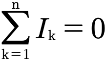
This law is justified by the conservation of charge. The amount of charge entering a some must be the same as the amount of charge leaving. Since current is nothing more than the change of charge with time this translate into current also being conserved in those same areas.
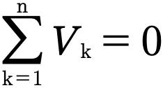
The second of these rules is as follows. The sum of the voltages across any element in a closed loop must be zero. As we did with the current law we will write this law down mathematically.
Gallery 1.11 The Imaginary Circuit
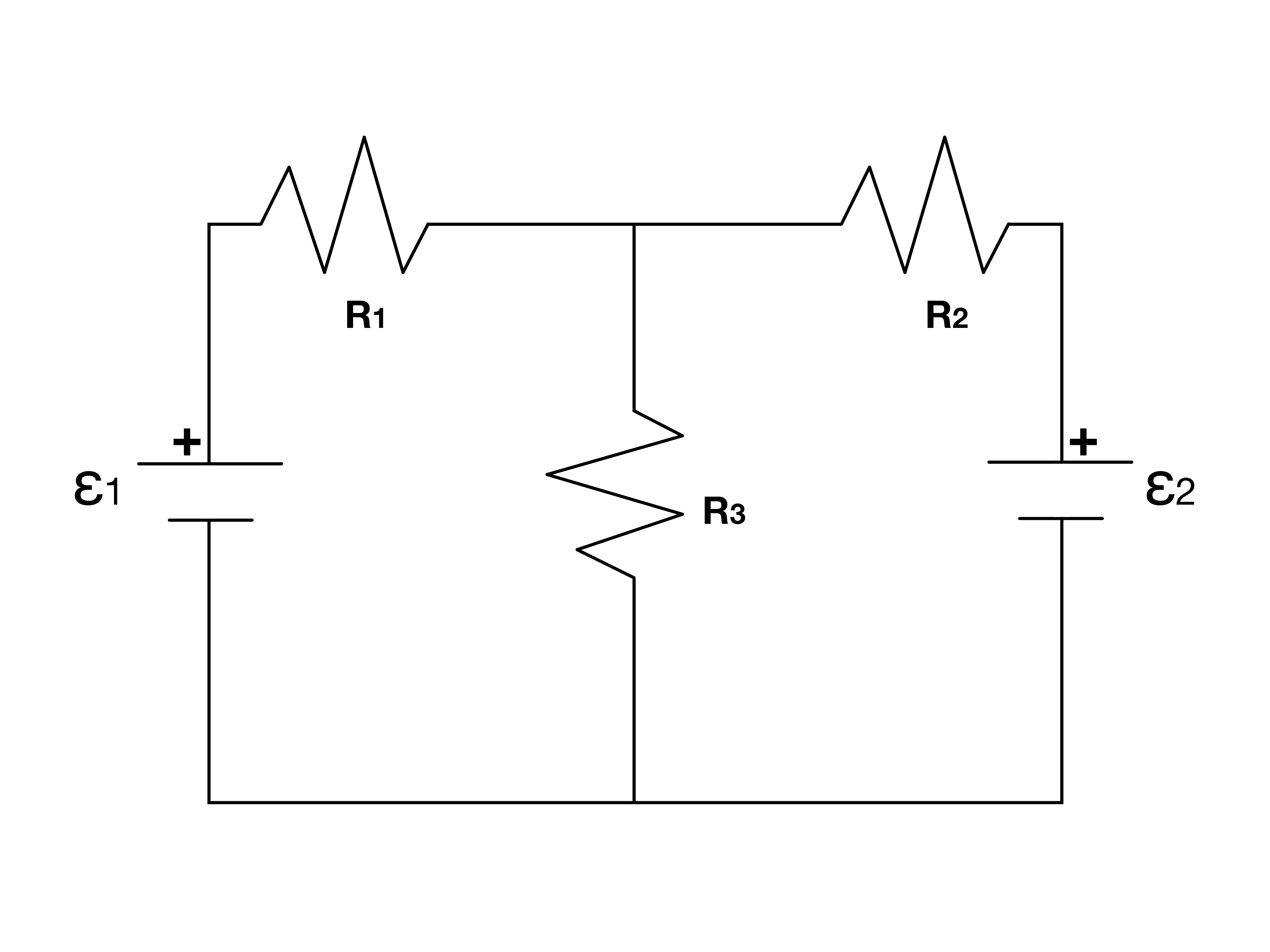
This is a typical circuit for which Kirchhoff’s Rules may be applied. Notice how there are multiple emf’s and loops. This indicates that Kirchhoff’s Rules should probably be used on the circuit.
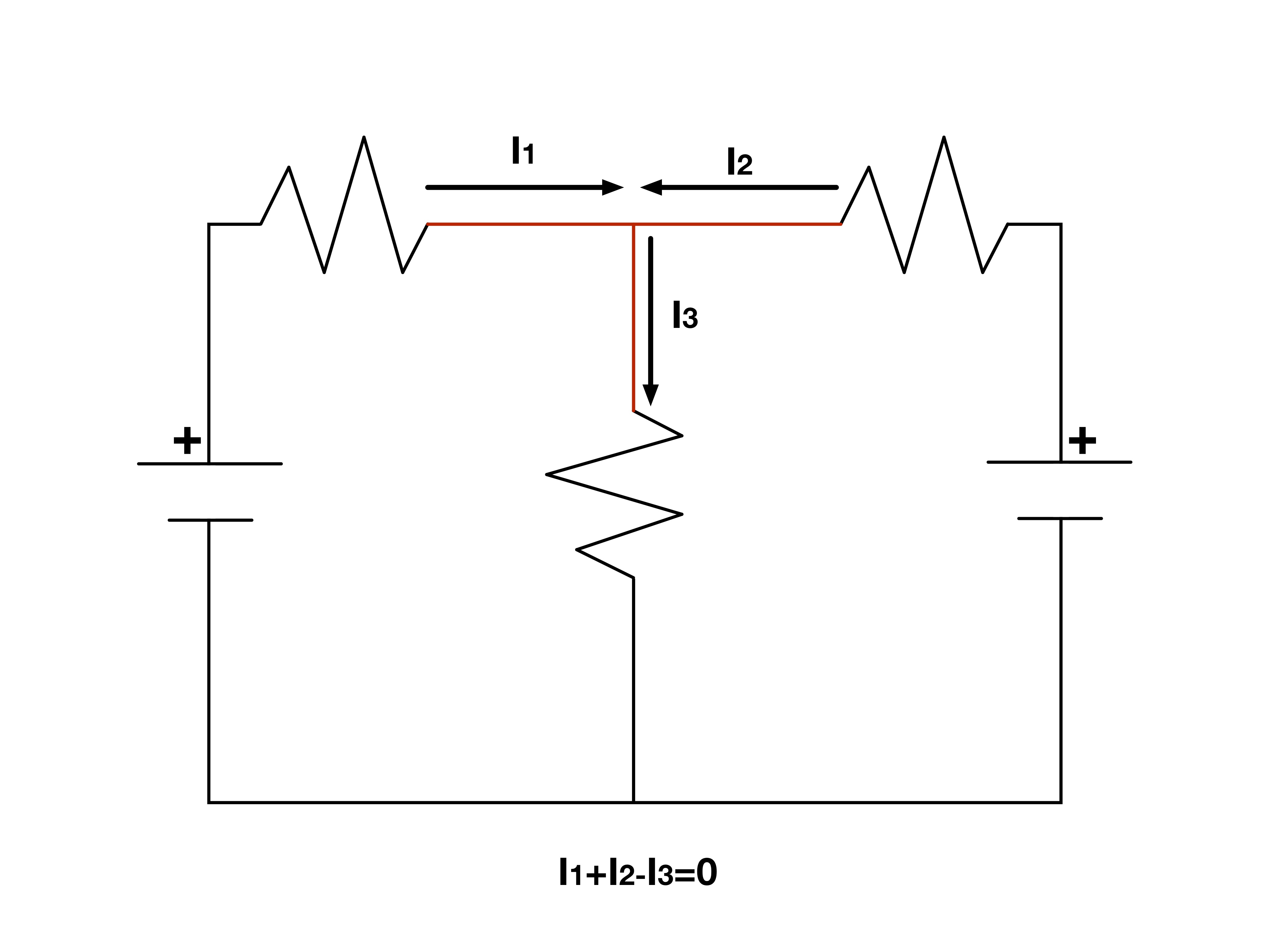
Here we suppose at the red node current 1 and 2 are flowing in and current 3 is flowing out. When we sum the currents together we give current 3 a negative sign indicating that it is flowing away from the node.
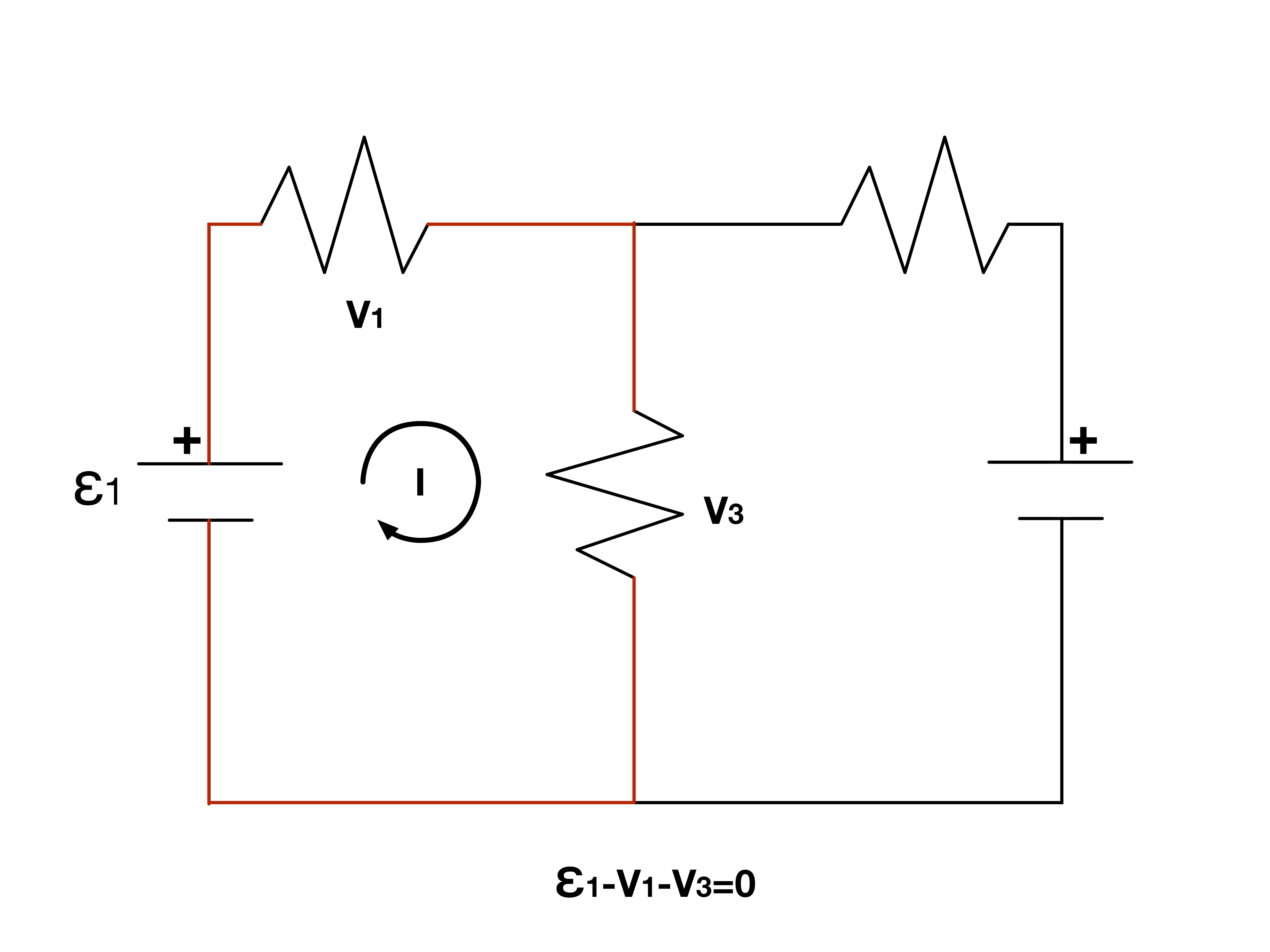
When summing the voltages across the elements in a loop it is important to state which way you think the current is flowing in that loop. In this case we say that the current is flowing clockwise through the left loop.
Although Kirchhoff’s Laws may be relatively straightforward applying them is another game entirely. For this reason we will discuss setting up the equations in some more detail before preceding to the example problems.
The first thing we will discuss is the current at nodes. You must always set up a convention for what the sign of a current going out and what the sign of a current going in will be. For this book we will say that currents going into a node are positive while currents coming out of a node are negative.
The direction of these currents are chosen on a feeling basis. When the math is all done and we interpret the results we will see that the math corrects our guess for us by making our current positive if we are right and negative if we were wrong with our guess while leaving the magnitude unchanged.
Now we will discuss the voltage equation. In figuring out equations for loops you must take into account several different variables. The first of these is in what way are you crossing an emf. If you cross an emf starting at the lower potential going to the positive you will have a positive voltage contribution from the emf. If instead you start at the positive and go to the negative you will have a negative emf voltage contribution.
Determining the voltage across a resistor can be a little trickier because it depends on what we have chosen the direction of the current to be. When moving against the current you will be adding voltage since you are moving from a lower to a higher potential. When moving with the current you will subtract voltage since you are moving from a higher to a lower potential.
After using the above to form the desired equations you can then solve for the missing information using your knowns.
Example 4.4.1
Use preserved Gallery4.4.2.1-1: three branches join common upper/lower nodes. Their upper-positive batteries are 1 V, 2 V, 1 V and resistors 2 Ω, 3 Ω, 2 Ω. Find branch currents with outer arrows upward and middle arrow downward.
Authored clarification: The unresolved placeholder is clarified by naming the actual preserved gallery and its values.
Reviewed worked solution:
Set lower potential zero and upper V.
Solve the independent junction equation.
Convert signed branch currents to source arrows.
Answer:
Check: I₁+I₃=I₂ and all branches have the same node voltage.
Gallery 1.12 Example 4.4.1
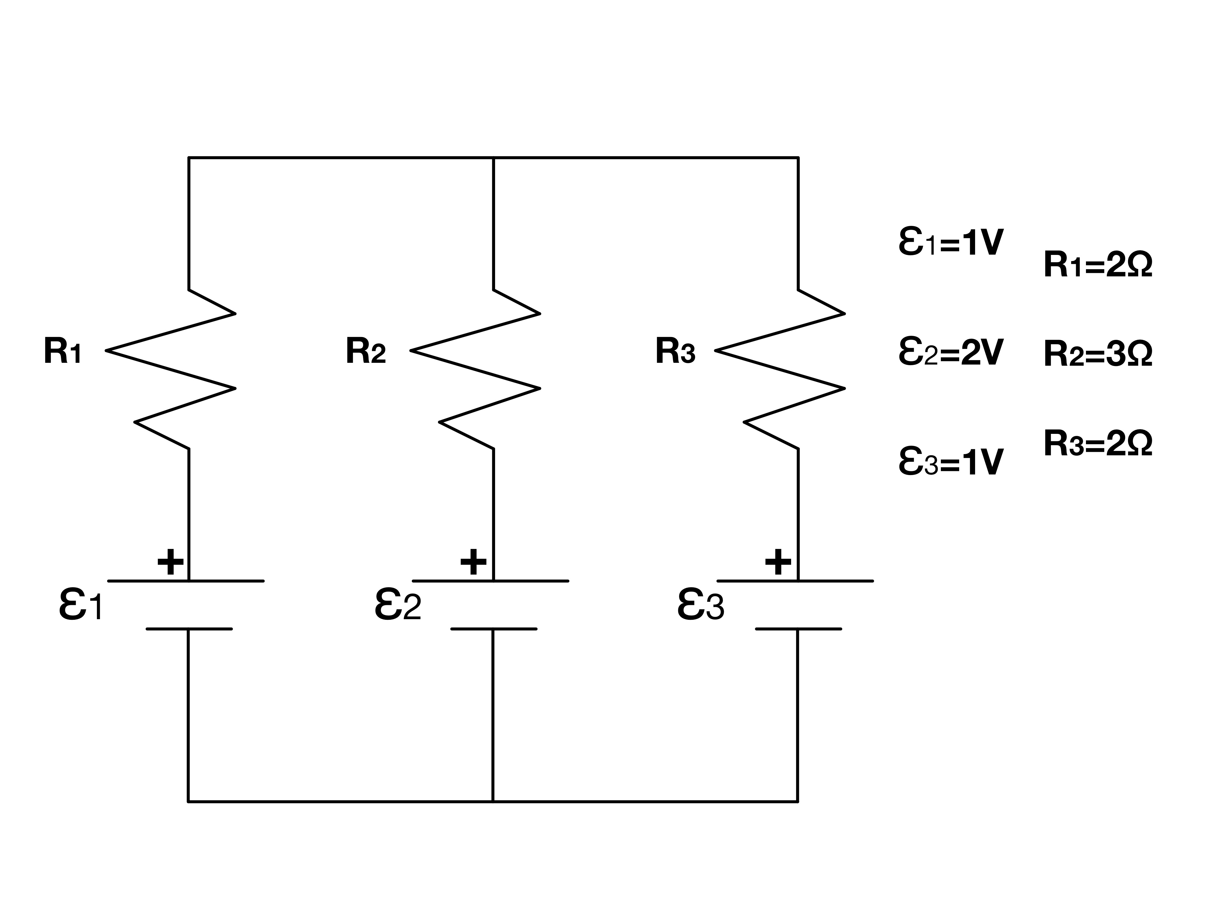
Here we have three rows of resistors each with an emf. This setup creates two loops and as you might guess the current through one or more of the emfs will have to be actually going against the potential.
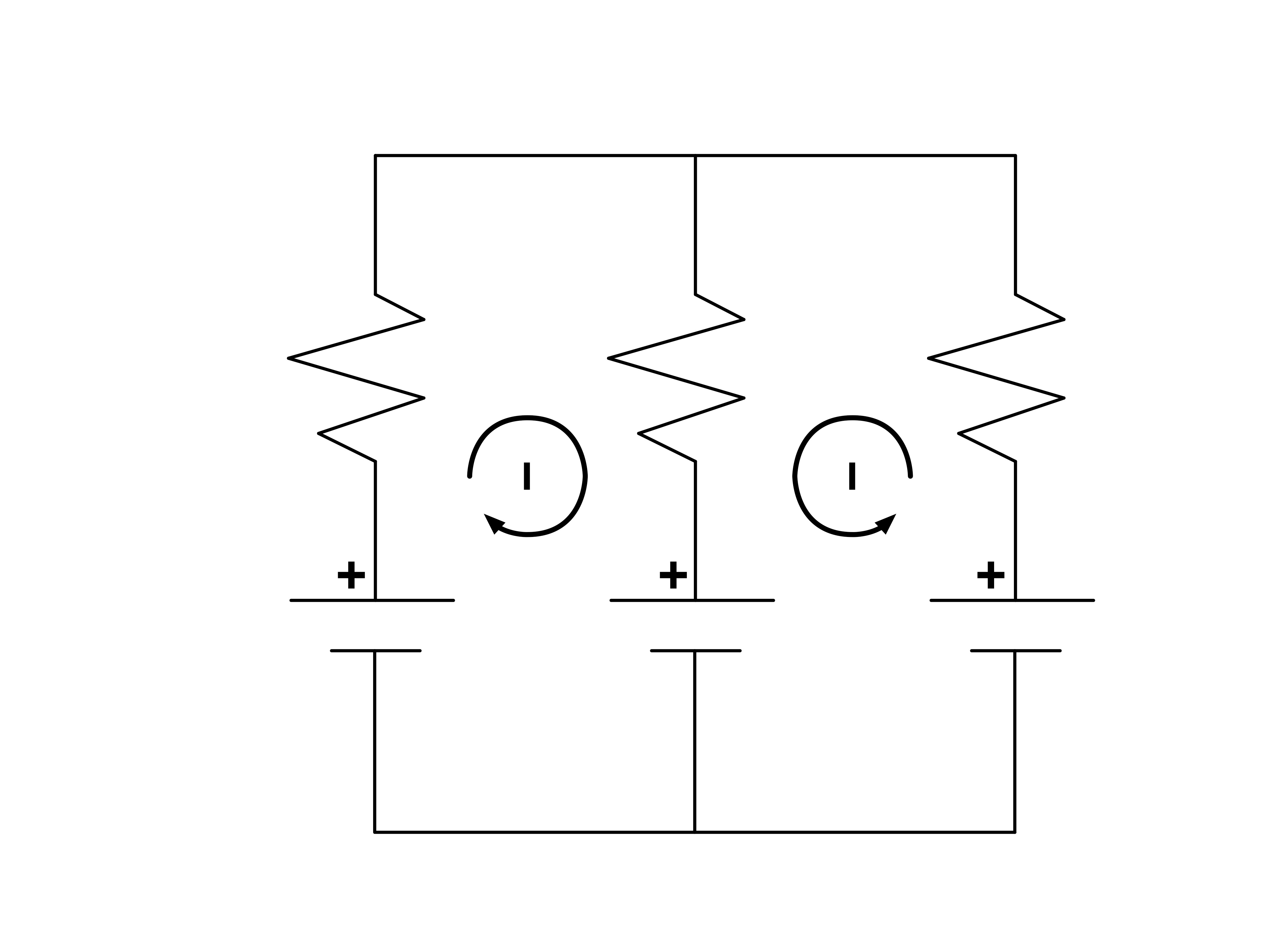
In this circuit we assume that the left loop has a clockwise current while the right loop has a counter-clockwise current. Although this assumption won’t effect magnitudes of our end result it will require us to consider the signs on those numbers.
Example 4.4.2
Authored explicit replacement for the unresolved diagram: an ideal emf drives R₁ in series with R₂ parallel R₃. Given I₂ through R₂, express emf.
Authored clarification: This supplied topology is an authored replacement rather than a recovered source diagram.
Reviewed worked solution:
Parallel branches have equal voltage.
Use the junction rule.
Add series drops.
Answer:
Check: All terms have units volts.
Gallery 1.13 Example 4.4.2
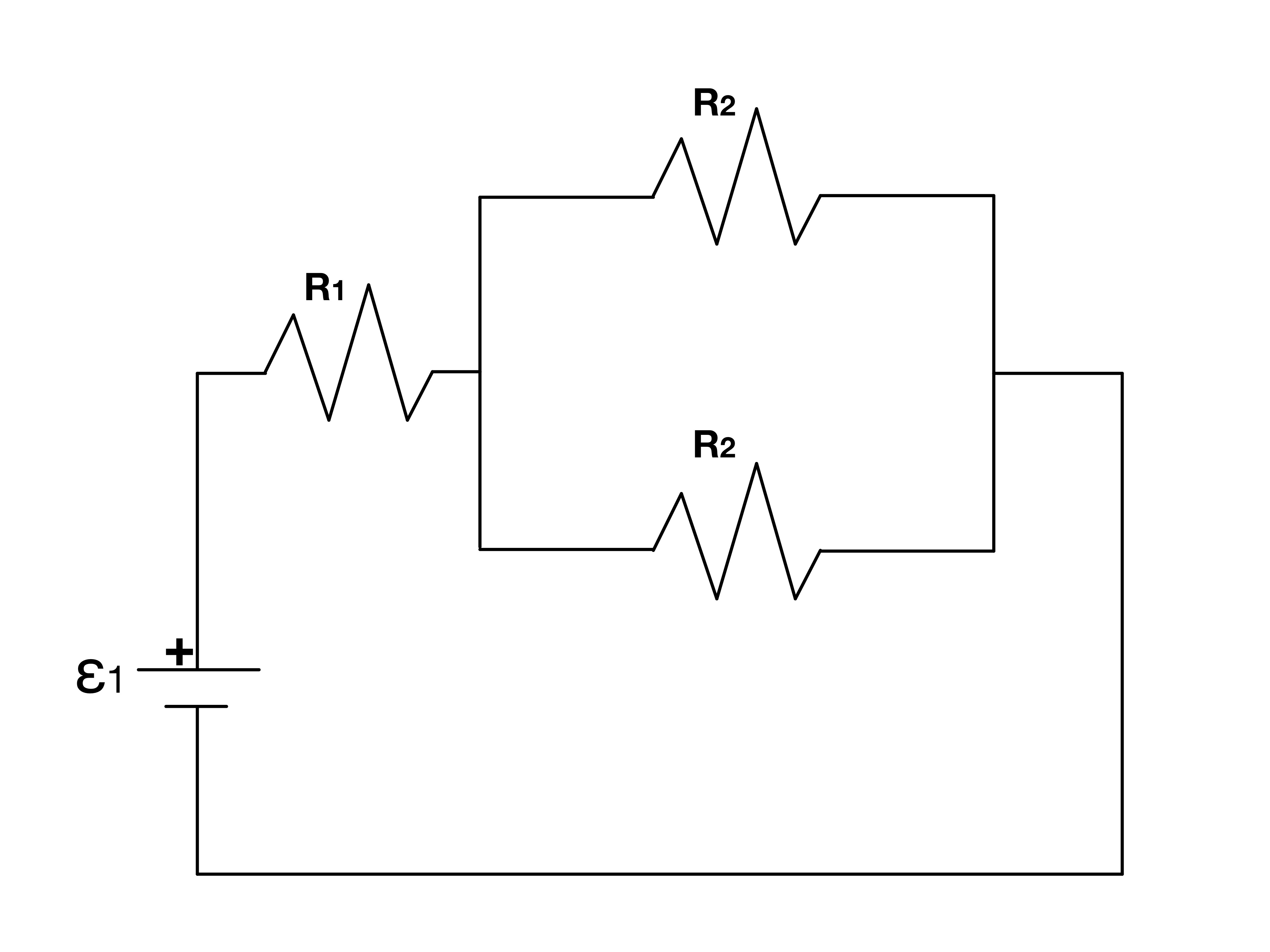
This is a circuit diagram you are already familiar with. Although many of these diagram for Kirchhoff’s Rules may look different than the diagrams used earlier some of them are actually the same.
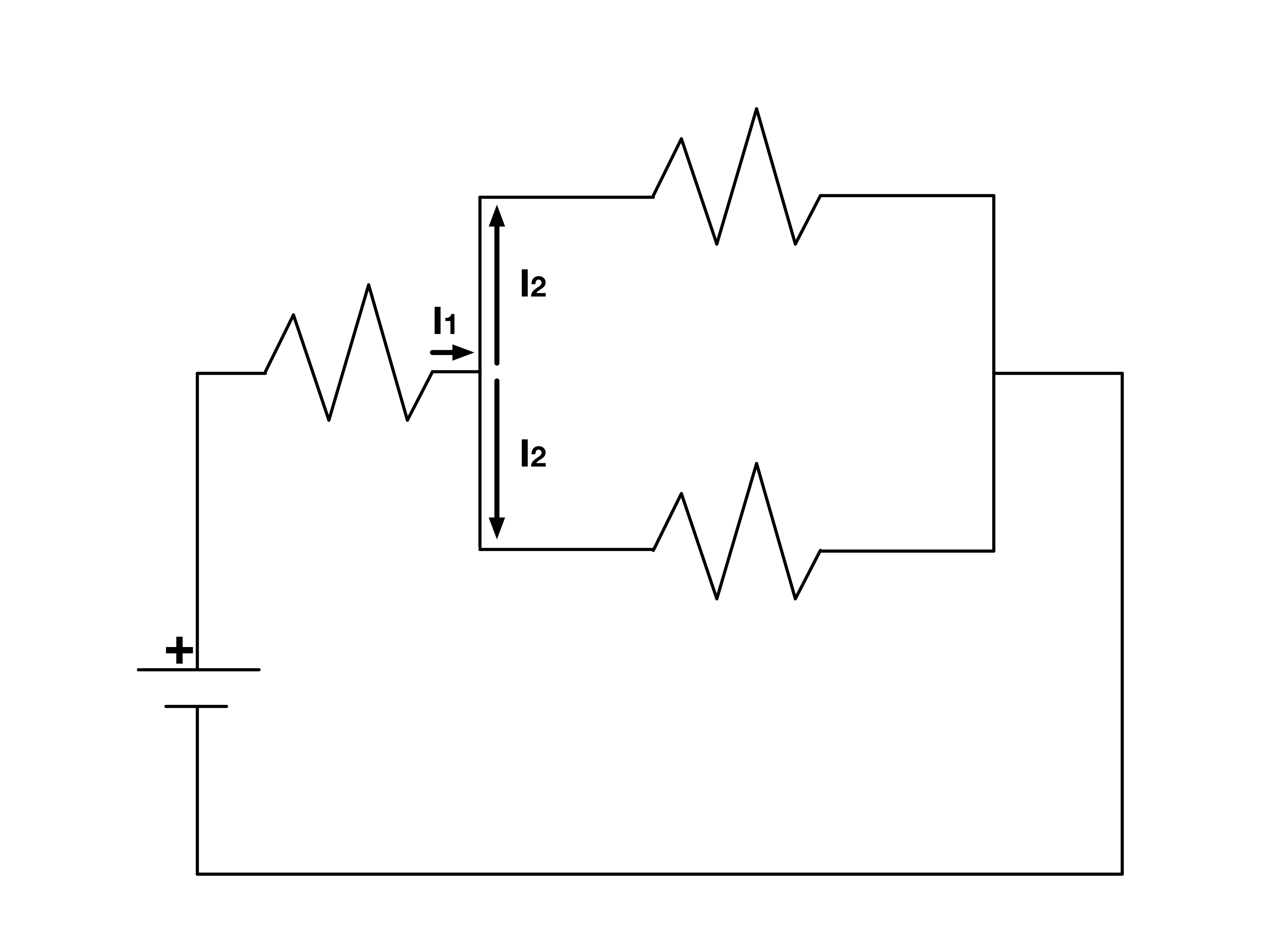
At this node we applied Kirchhoff’s Current law giving us the equation indicated in Example 4.4.2.
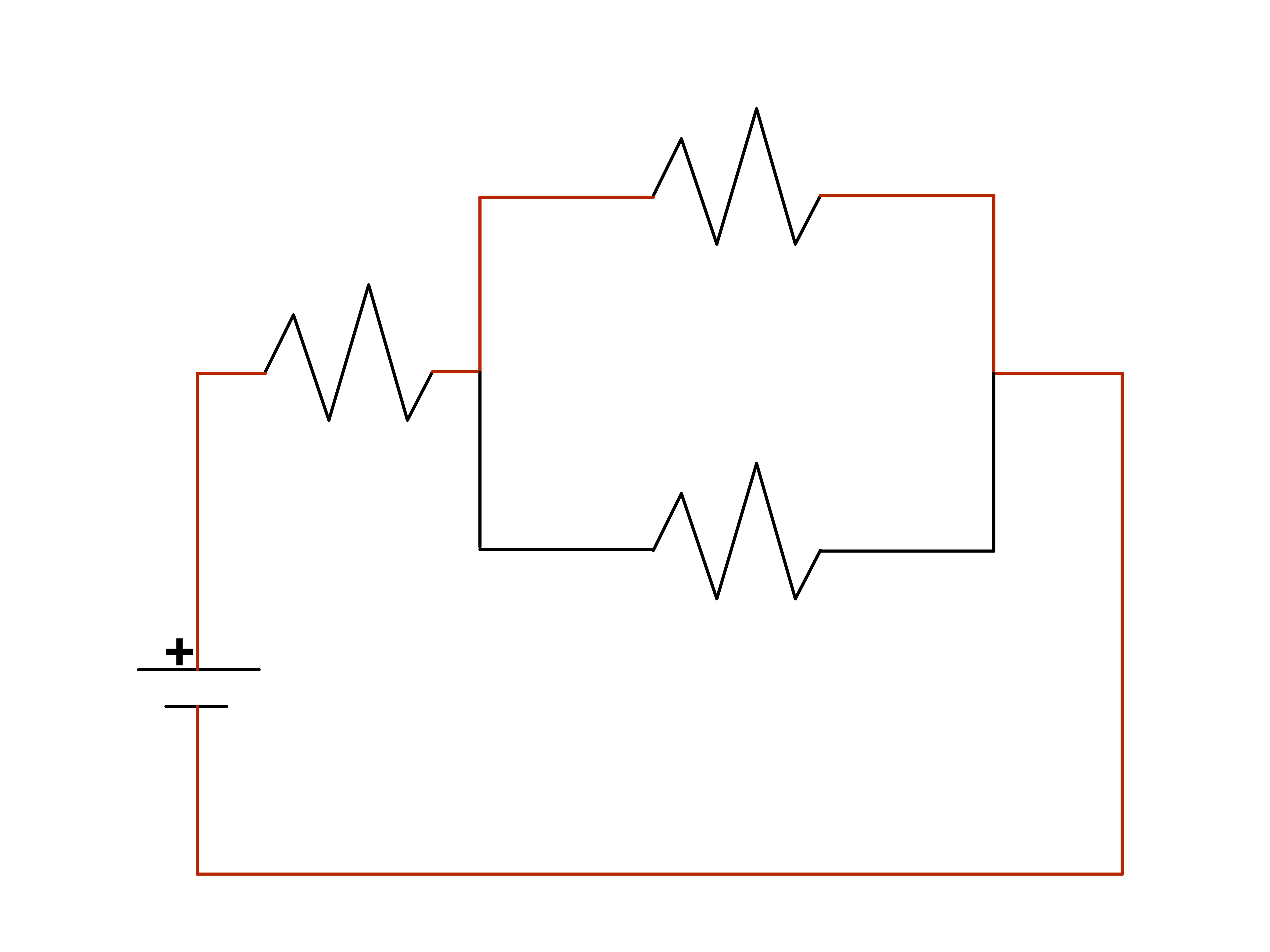
Using the loop with parallel resistors it is actually possible to form three different loops. The red traces the loop used in Example 4.4.2.
Now we can use the first equation we found relating the currents and make the appropriate substitutions to get the wanted equation. Since
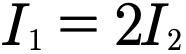
We can make a substitution for current one in our reworked loop equation to give us our answer

Review 1.4 Kirchhoff’s Laws
This review preserves the author’s recorded prompts, choices, and answer states. Corrected items have separate reviewed explanations and keys; unchanged draft keys are marked unreviewed. Unfinished items are not scored.
Original question 1
After solving a linear system obtained from Kirchhoff’s Laws what does having a negative value for a current mean?
Nothing. It is just an artifact of your original choices.
The actual current flows opposite to the reference direction chosen for the calculation.
That the initially chosen current direction is correct.
Something went wrong applying Kirchhoff’s Laws.
None of the above
Reviewed answer and reasoning
B
A reference direction is a valid bookkeeping choice. A negative calculated value means the actual current flows in the opposite direction; its magnitude is the absolute value of that calculated current.
The sign gives the physical direction relative to the chosen reference arrow.
Archived original question and recorded key · contains the source error
After solving a linear system obtained from Kirchhoff’s Laws what does having a negative value for a current mean?
Nothing. It is just an artifact of your original choices.
The direction you originally chose for that current is incorrect.
That the initially chosen current direction is correct.
Something went wrong applying Kirchhoff’s Laws.
None of the above
Original recorded key: B
Original question 2
A current enters a node and is split in three unequal ways. What equation would properly describe this?
None of the above
Reviewed answer and reasoning
D
Given one incoming I1 and outgoing I2,I3,I4, KCL I1-I2-I3-I4=0.
The independent semantic audit confirms this source prompt and recorded key under its stated conditions.
Archived original question and recorded key · contains the source error
A current enters a node and is split in three unequal ways. What equation would properly describe this?




None of the above
Original recorded key: D
Original question 3
When passing through a resistor moving in the direction of the current what sign would you expect to have on your voltage?
Negative
Positive
Reviewed answer and reasoning
A
Potential change through positive resistance in current direction is -IR.
The independent semantic audit confirms this source prompt and recorded key under its stated conditions.
Archived original question and recorded key · contains the source error
When passing through a resistor moving in the direction of the current what sign would you expect to have on your voltage?
Negative
Positive
Original recorded key: A
Original question 4
What sign will you get for your emf voltage if you move from the positive to the negative side.
Positive
Negative
Reviewed answer and reasoning
B
Traversing ideal battery from positive to negative gives -emf.
The independent semantic audit confirms this source prompt and recorded key under its stated conditions.
Archived original question and recorded key · contains the source error
What sign will you get for your emf voltage if you move from the positive to the negative side.
Positive
Negative
Original recorded key: B
Original question 5
Traverse two ideal opposing sources: cross ε₁ from − to + and ε₂ from + to −. What is the algebraic emf change?
Reviewed answer and reasoning
A
The traversal sets the signs. If only the strength were requested, the magnitude would be |ε₁−ε₂|.
This reviewed version states the assumptions or convention needed for one determinate answer. The archived source prompt and key are retained.
Archived original question and recorded key · contains the source error
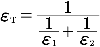
Consider a circuit composed of a single loop, two oppositely facing batteries, and a resistor. Find an expression for the circuits total emf in terms of the batteries emfs.



None of the above
Original recorded key: A
Reviewed worked examples
These authored derivations are paired with the original example identities. Added assumptions are stated.
Example 4.4.1 · reviewed solution
Use preserved Gallery4.4.2.1-1: three branches join common upper/lower nodes. Their upper-positive batteries are 1 V, 2 V, 1 V and resistors 2 Ω, 3 Ω, 2 Ω. Find branch currents with outer arrows upward and middle arrow downward.
Authored clarification: The unresolved placeholder is clarified by naming the actual preserved gallery and its values.
Set lower potential zero and upper V.
Solve the independent junction equation.
Convert signed branch currents to source arrows.
Check
I₁+I₃=I₂ and all branches have the same node voltage.
Example 4.4.2 · reviewed solution
Authored explicit replacement for the unresolved diagram: an ideal emf drives R₁ in series with R₂ parallel R₃. Given I₂ through R₂, express emf.
Authored clarification: This supplied topology is an authored replacement rather than a recovered source diagram.
Parallel branches have equal voltage.
Use the junction rule.
Add series drops.
Check
All terms have units volts.
Glossary and deeper reading · 4 refreshers
These editorial refreshers supplement the reading. Definitions and examples are added guidance; original source wording and recorded answers remain in their original context.
-
Electric charge
Electric charge is a conserved property that determines electric interactions. It can be positive or negative and is measured in coulombs; ordinary net charges arise from an imbalance of charged particles. For example, transferring electrons between initially neutral objects leaves one negatively charged and the other positively charged.
-
Electric current
Electric current is the net rate of charge flow through a specified cross section. It is measured in amperes, or coulombs per second, with direction defined by positive-charge motion. For example, the same steady current passes through each element of a simple unbranched series loop.
-
Potential difference
Potential difference is the change in electric potential between two locations. It represents electric potential-energy change per unit charge and is measured in volts. For example, the potential difference across a resistor describes the energy transferred per coulomb passing through it.
-
Electromotive force
Electromotive force is energy supplied per unit charge by a source or induction process. Despite its name it is measured in volts, rather than newtons, and can exist even when no current flows. For example, an ideal battery supplies an emf while an induced emf can be produced by changing magnetic flux.