Capacitors in Circuits
Original source retained for reference; this draft does not establish AP coverage.
Original author draft. Original wording and recorded answer states are preserved without claiming reviewed scientific correctness or AP alignment.
Physics 2 original textbook · Chapter 4
Section 2
Capacitors in Circuits
Capacitors are extremely common devices in circuits and chances are if you opened up any one of your electrical devices you would find one (if not several). As a result understanding how they work when placed in a circuit is extremely important in understanding how the electronics you work with day to day function.
When a lone capacitor is placed inside an idealized circuit the capacitance of that capacitor will stay the same and the voltage across it will become that of the emfs voltage. This is not true of two or more capacitors inside a circuit.
The goal of this section is to describe the total capacitance of some network of capacitors in terms of a single capacitance. Doing so requires us to consider the network of capacitors as a single capacitor with its own charge and voltage which although might seem strange now should soon become clear.
To begin we will discuss capacitors in parallel. A parallel connection is a network of capacitors arranged so that they share their input and output wires. In such a connection it is conceivable to have any number of capacitors connected.
The first thing to notice about the parallel connection is the nature of the voltage. Here we must realize two things. That the input and output connections of parallel capacitors are shared and that the wire connecting the capacitors is itself a conducting medium. Since the wire is a conducting medium it will be at an equipotential when the capacitors are fully charged. The fact that the capacitors all then have the same inputs and outputs means that they much all have the same voltage across their plates so that for a two capacitor setup we have

The second thing to look into is the relationship between the charges on the capacitors. Here we must say that the charge on the fictitious combined capacitor must be the sum of the charges on the smaller capacitors so that
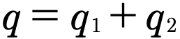
If we then substitute in for q using the equation
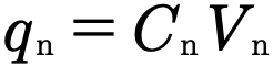
and then recalling that all voltages are equal we get that

or

Therefore to get the capacitance of multiple capacitors in parallel we simply add them together.
Gallery 1.4 Parallel Capacitors
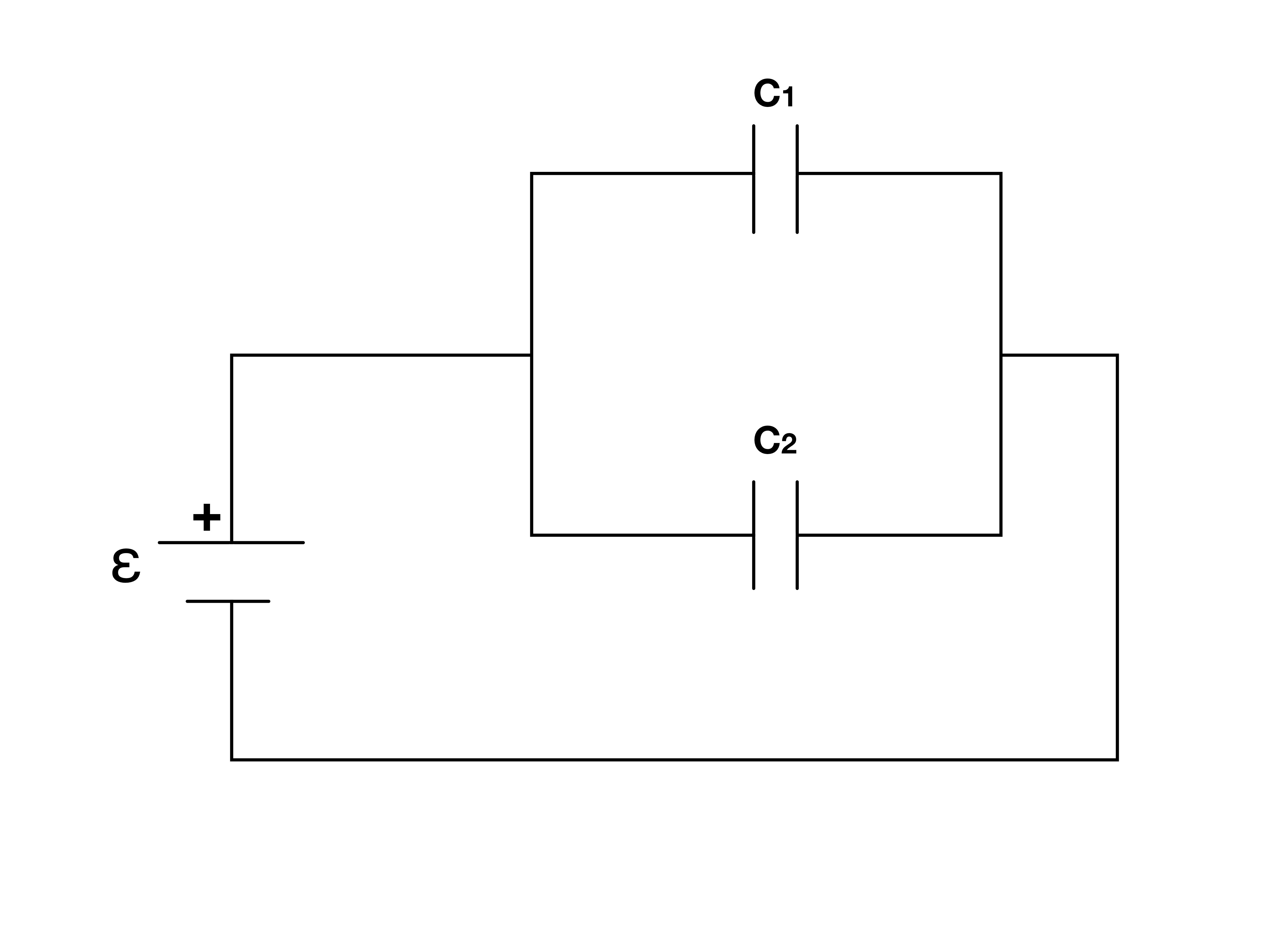
In a parallel connection two elements are placed “side-by-side”.
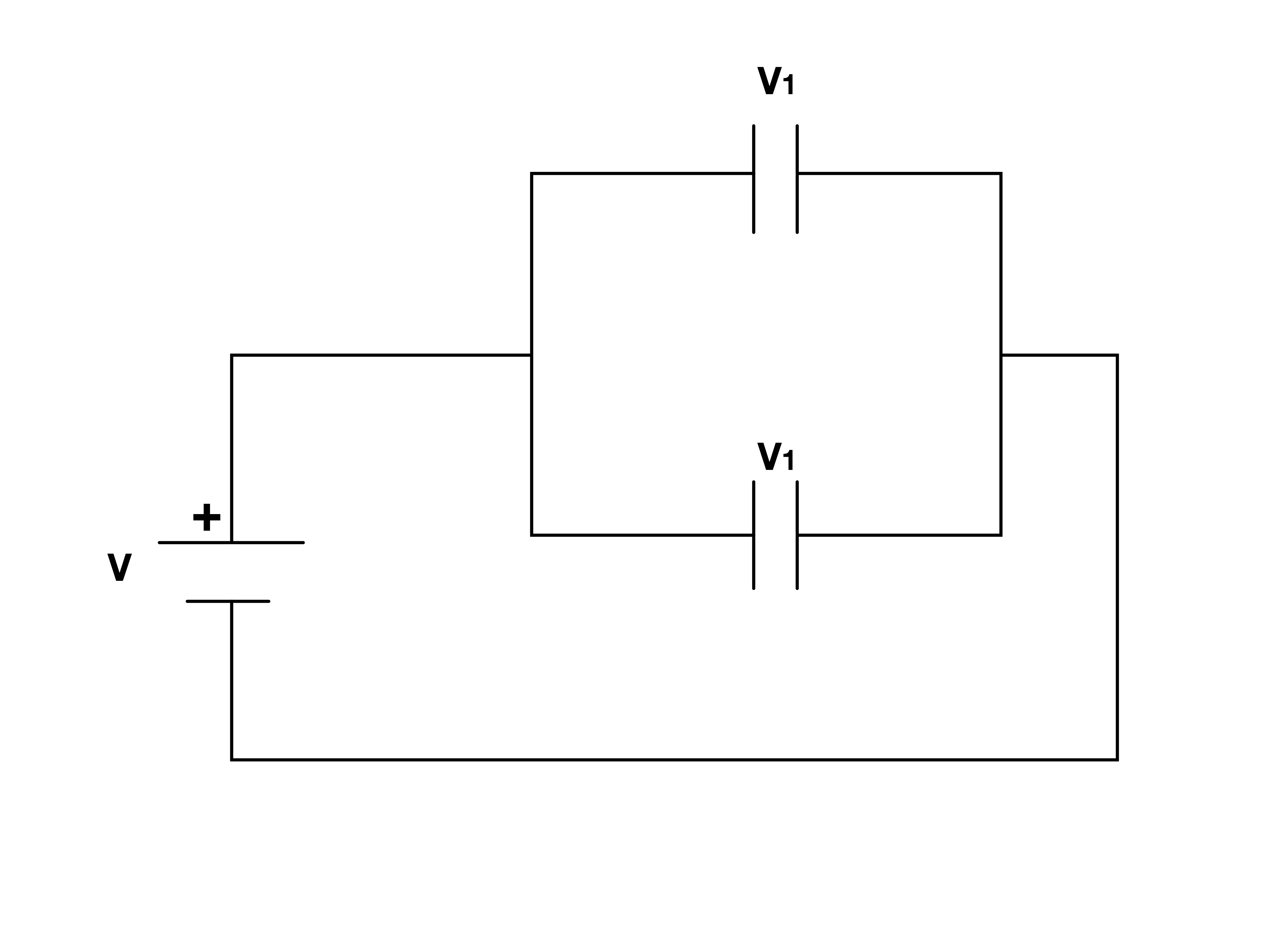
For parallel capacitors the sum of the voltages on each capacitor is the same. This happens as a result of the conducting nature of the wires. A perfect conductor will hold a constant potential.
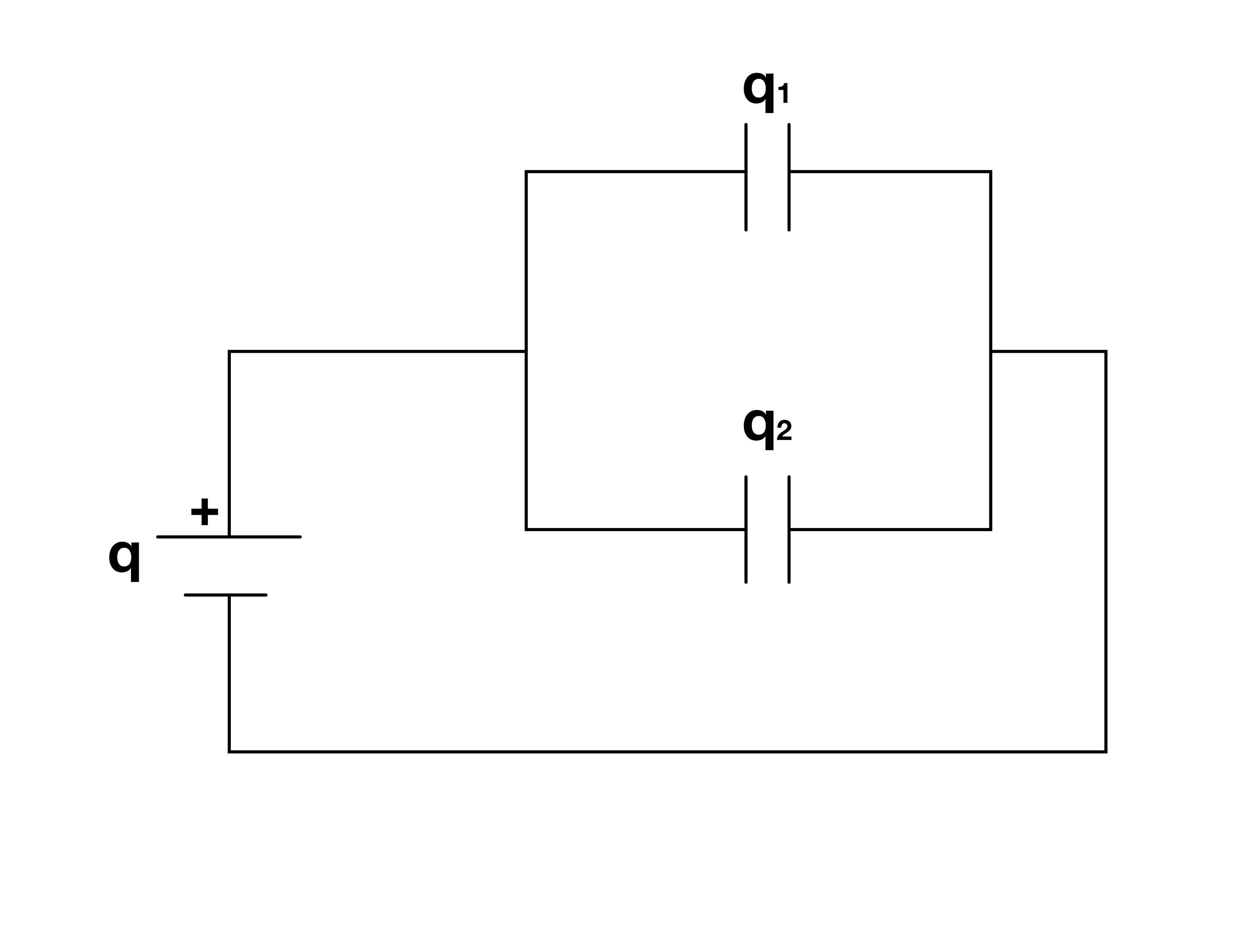
In parallel connected capacitors the charge on each of the capacitors sums to a single amount of charged. Charge conservation tells us that the “incoming” charge must be divided amongst the capacitors in the parallel connection.
The second type of connection that we deal with is called the series connection. In a series connection capacitors are placed back to back. Like the parallel connection we will have to analyze the circuit setup to determine the resulting capacitance.
The first thing we will again look at is the voltage. For a setup in which we have two capacitors in series connected to an emf we will have three different wire segments. Since each wire is itself a conductor each wire will have a particular equipotential. These potentials are not necessarily all the same. If we give a potential P₊ to the wire connected to the positive pole of the emf, a potential P to the middle wire, and a potential P₋ to the wire connected to the negative pole of the emf then for the sum of the voltages across each capacitor we get that
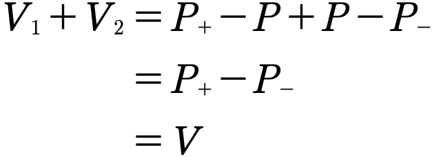
or

The second thing we will look at is charge. As we know from previous discussion when charge is placed on one conductor an equal amount of charge is induced on a corresponding conductor. For capacitors in series this rule holds as well so that each capacitor has the same charge.

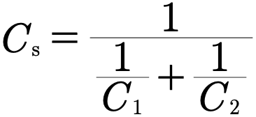
Taking this information we can now determine the capacitance of two capacitors in series by solving the capacitance equation for V and recalling that for capacitors in series charge is equal.
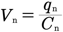
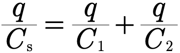
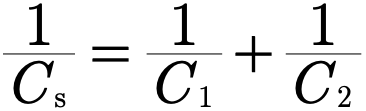
or in a more straightforward form
Gallery 1.5 Capacitors in Series
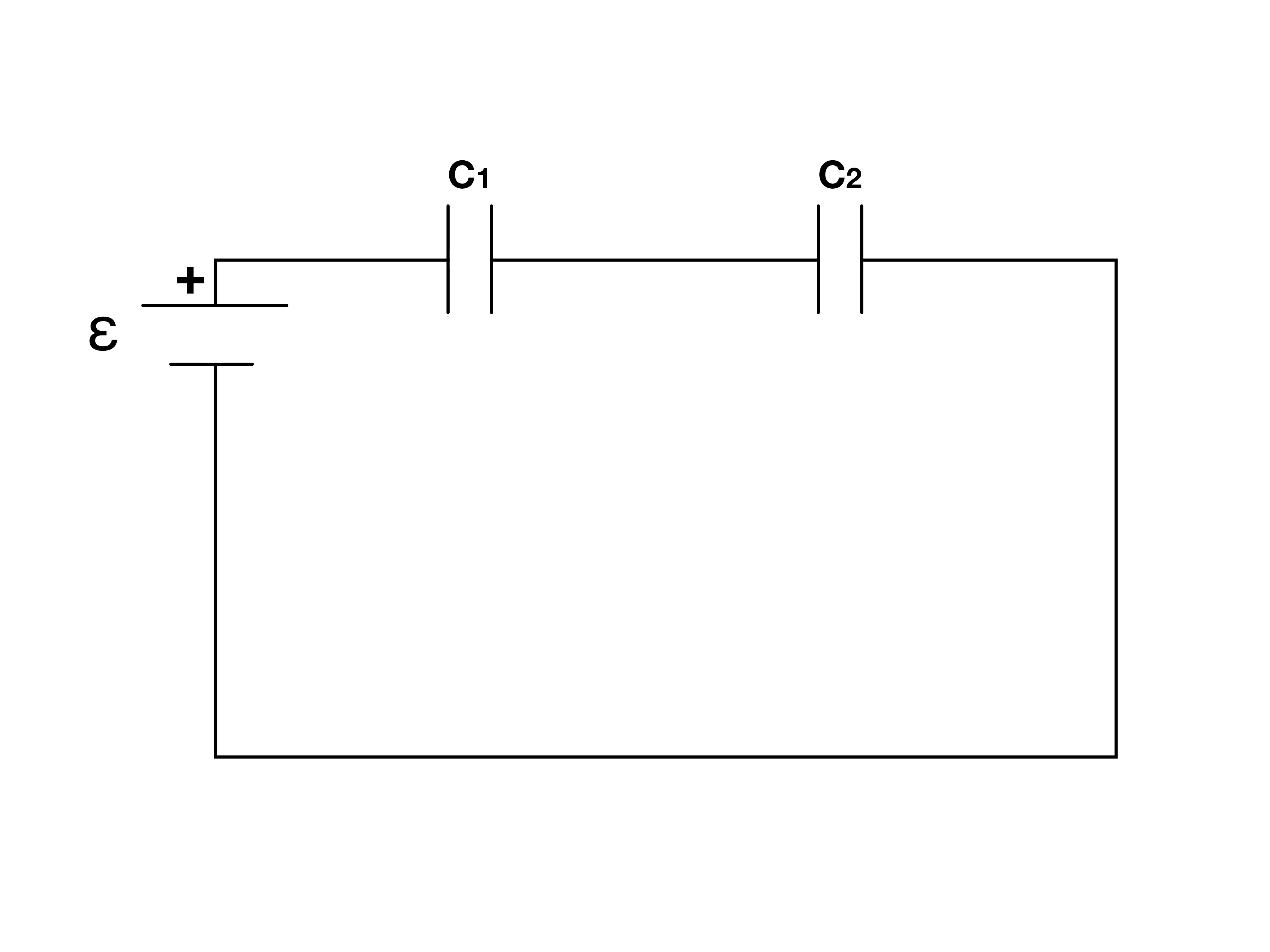
In a series connection circuit elements are placed “back-to-back”.
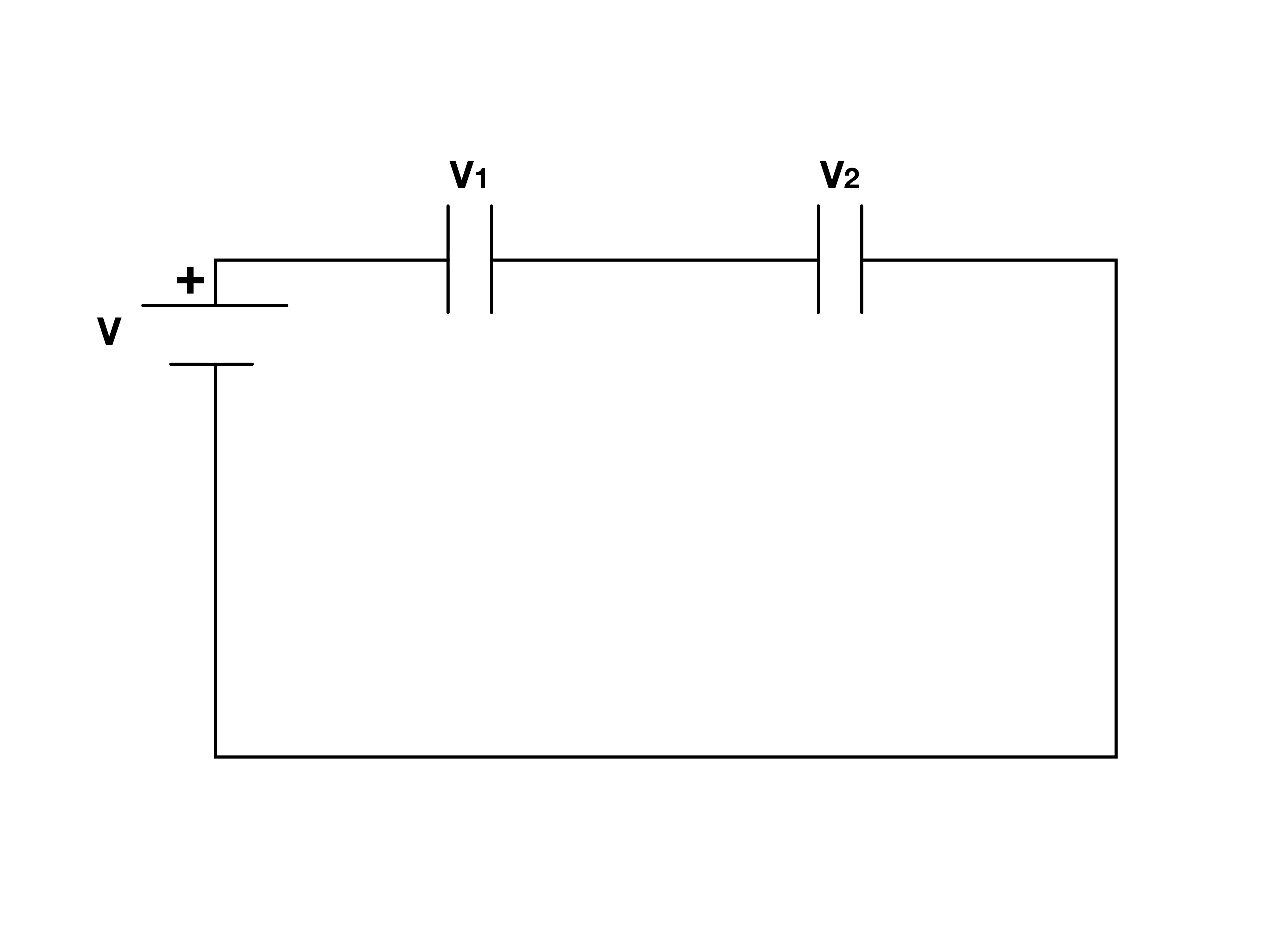
Here the multiple wire segments create several different voltages. Since the emf creates a particular voltage across the entire circuit the sum of the voltage across each capacitor must equal the emfs voltage.
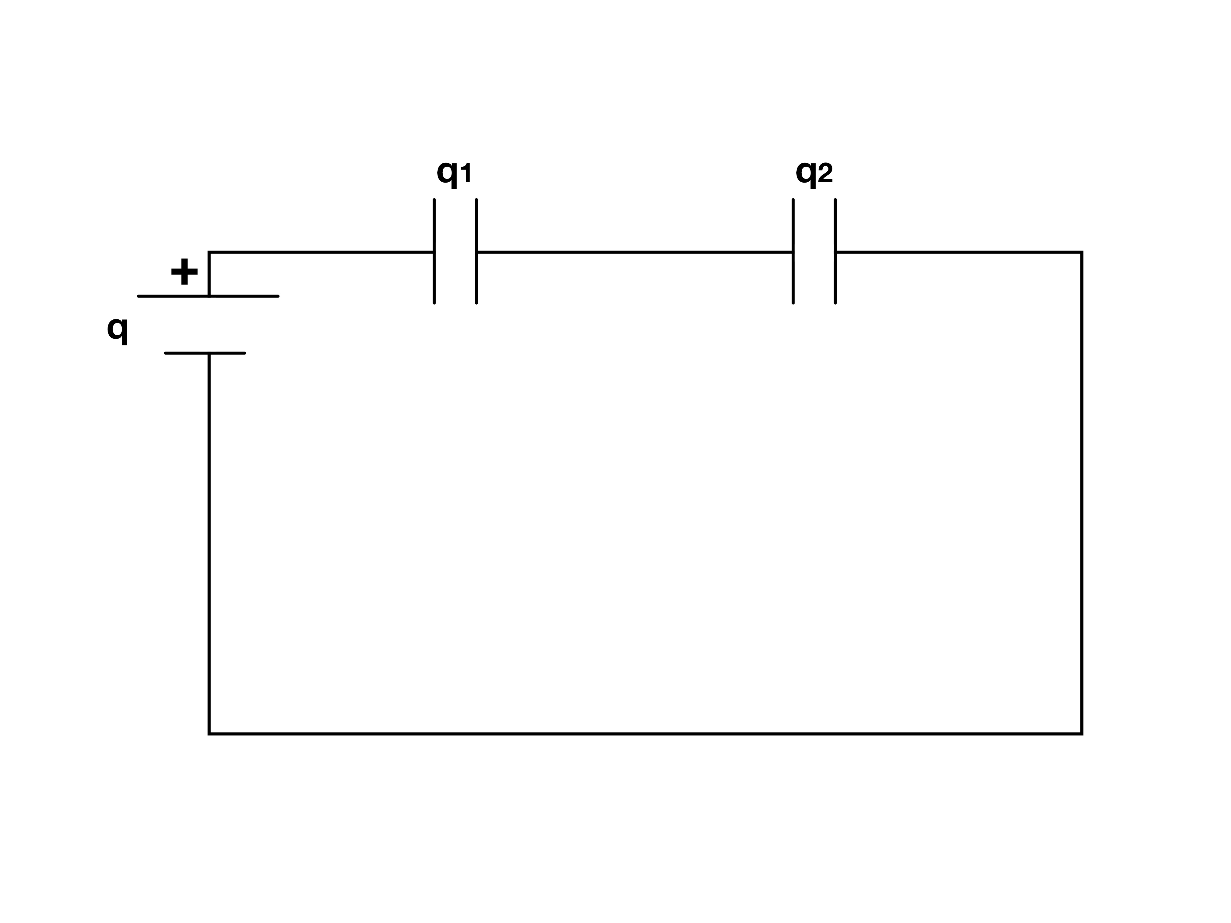
In a capacitor each plate will gain a certain charge which induces an opposite charge on the other plate. For capacitors in series this effect occur doubly so carrying the charge from capacitor to capacitor.
Example 4.2.1
Three 2 F capacitors form one lone capacitor in series with a parallel pair. Find Ceq.
Authored clarification: The source’s count says four, but the described network has three; this prompt states the intended described topology.
Often times each capacitor in a circuit is given a particular name so that they are easy to keep track of. In this problem we will name the non-parallel capacitor

and the parallel capacitors
 ,

To begin we will look at the capacitance of the parallel capacitors. For parallel capacitors we simply have to add the capacitances together.

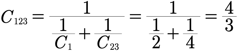
This now allows us to treat the lone capacitor as in series with a single capacitor with the capacitance of the parallel capacitor. The formula for capacitors in series is a little more cumbersome as you may recall.
Gallery 1.6 Example 4.2.1
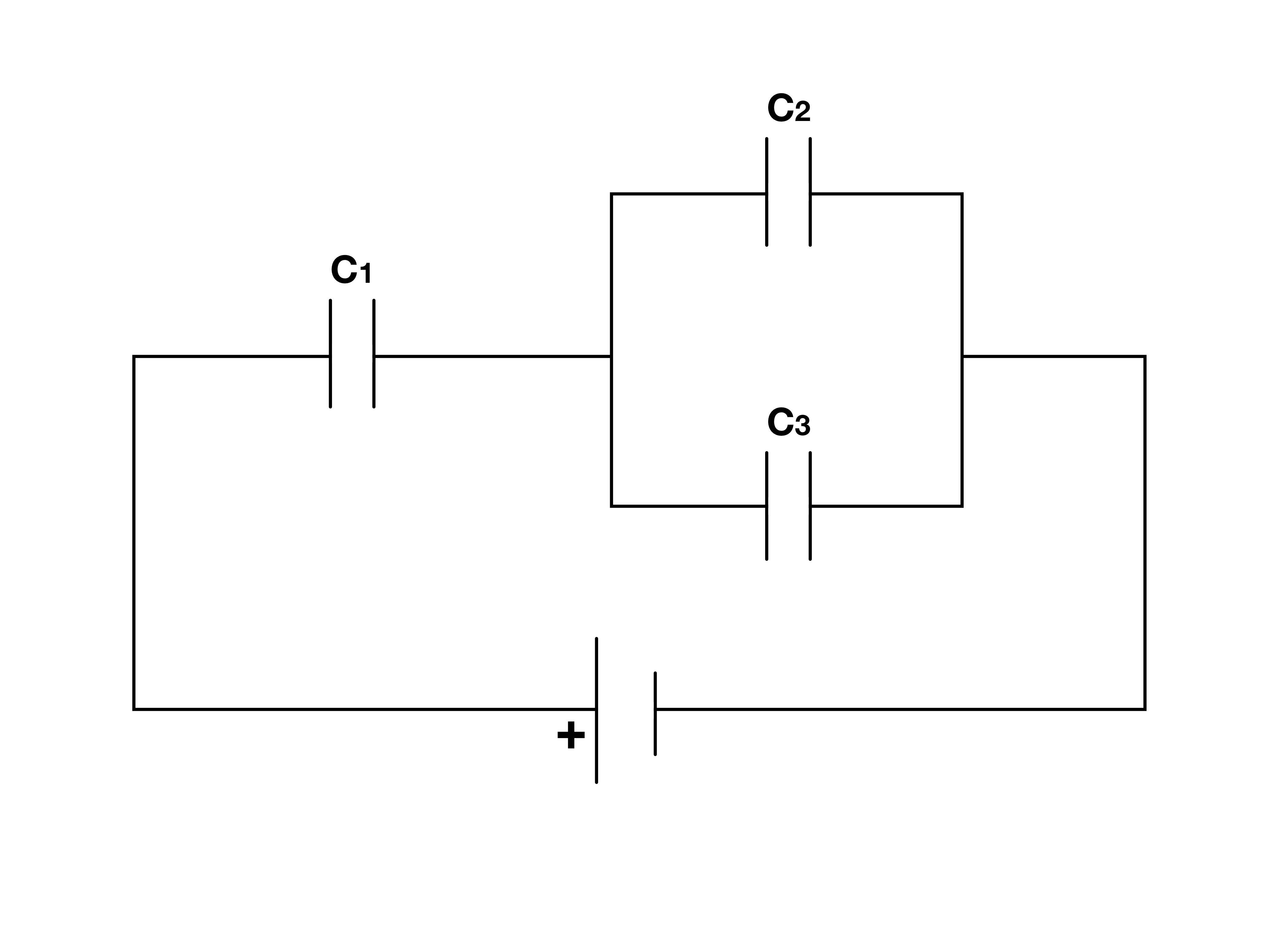
Here is the circuit used in example 4.2.1. We begin by considering the two capacitors in parallel.
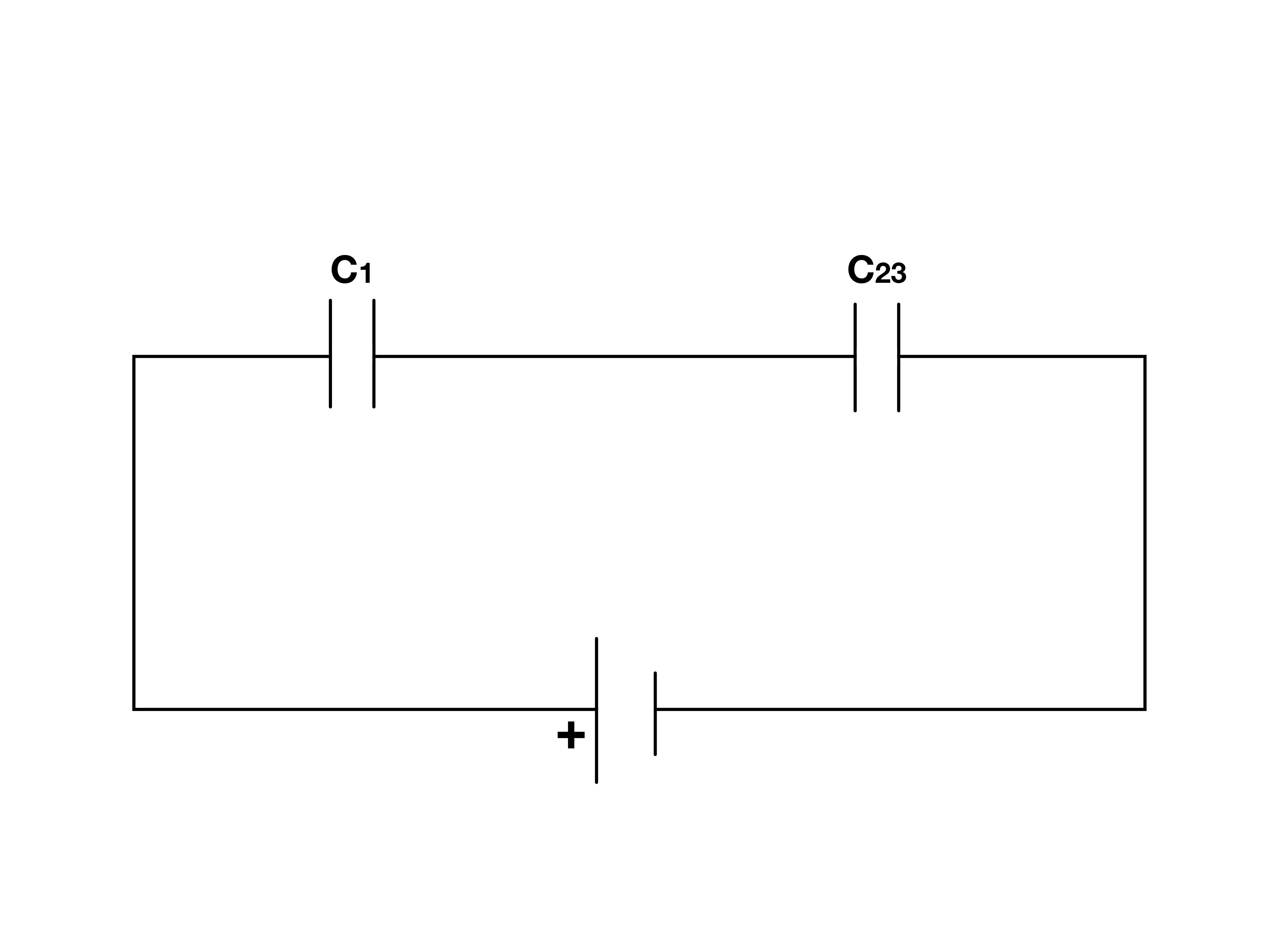
Once we reduce the capacitors in parallel to a single capacitor we can look at the two capacitors in series to determine the total capacitance of the circuit.
Example 4.2.2
A 3 F capacitor is parallel to two 2 F capacitors in series. The supply is 2 V. Find the voltage on either series capacitor.
Authored clarification: Ideal capacitors; the intermediate conductor is initially neutral.
This example demonstrates the power of the rules we have just derived. Given capacitances and the voltage of an emf we can determine the voltage on any particular capacitor in a network.
We will call the capacitors in series
 ,

and the lone capacitor in parallel with the other two

To approach this problem we first choose something which has the desired voltage in it.
The voltage of capacitor 2 using the capacitance equation reads
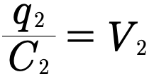
To figure out the voltage all we then have to do is figure out the charge on the capacitor. We know from previous analysis that the charges on the capacitors in series will be the same and that the charge of capacitors in parallel must sum to the charge of the entire circuit. This means that we can write the following equation.
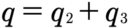
If we solve for the charge on the second capacitor we then have

which can substituted into the voltage equation for capacitor 2.
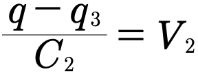
Now we don’t know what the q’s are directly but we can get expressions for them using the corresponding capacitance equations for the appropriate circuits.
Making this substitution gives us that
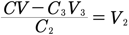
Now we have one final thing we need to deal with. Everything but the third capacitors voltage is known at this point but we do have one last trick at our disposal. Since capacitor 3 is in parallel with the capacitors in series and directly connected to the emf its voltage is nothing more than the emfs voltage
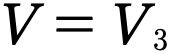
Plugging this in we get an expression of the voltage on the second capacitor in terms of only known values.
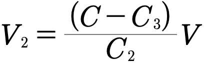
Therefore

Gallery 1.7 Example 4.2.2
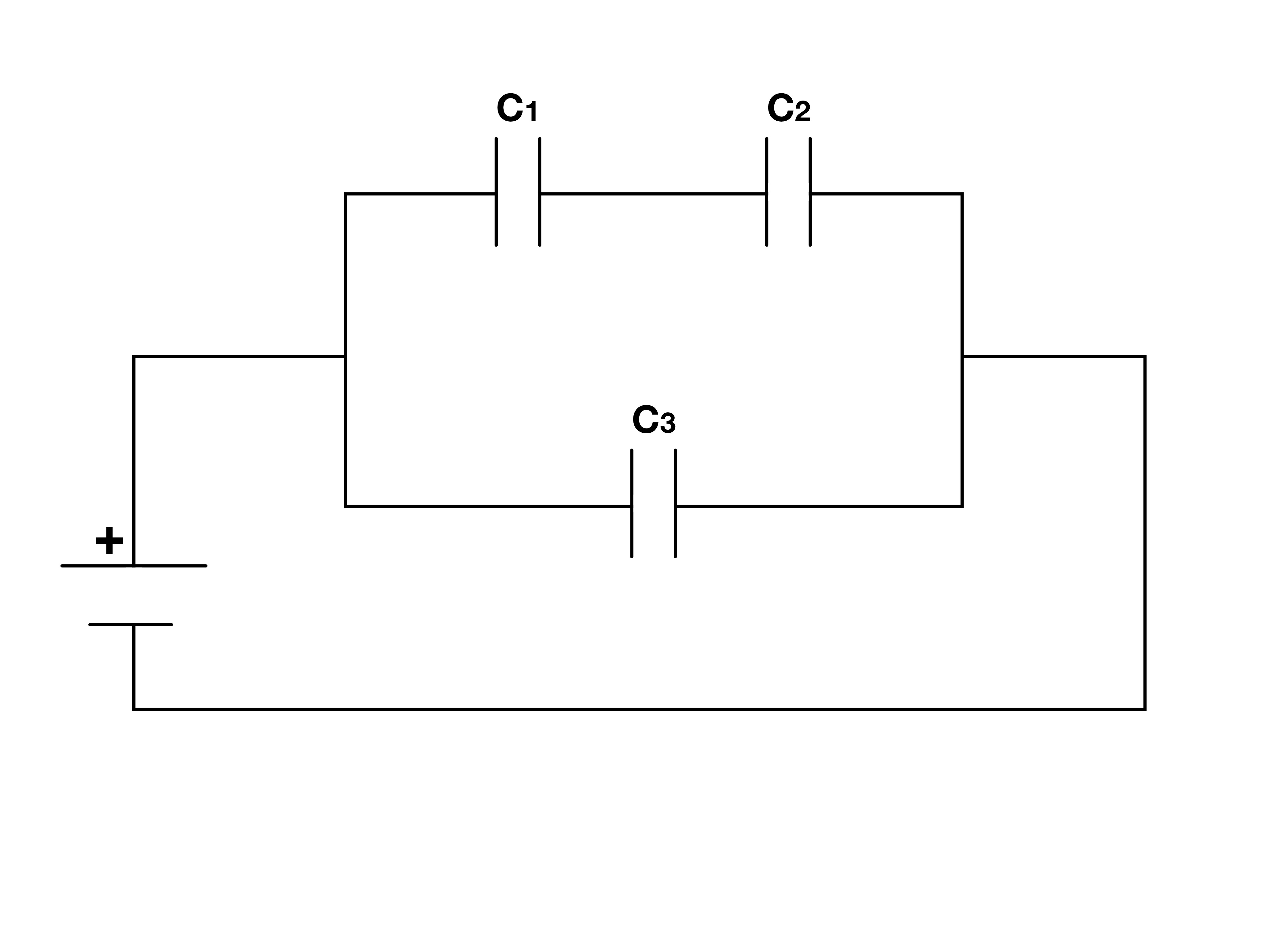
This is the circuit diagram to be used with Example 4.2.2. In this problem we look for the voltage across C2 using the rules which govern the function of capacitors.
Review 1.2 Capacitors in Circuits
This review preserves the author’s recorded prompts, choices, and answer states. Corrected items have separate reviewed explanations and keys; unchanged draft keys are marked unreviewed. Unfinished items are not scored.
Original question 1
Using the same specified set of positive ideal capacitances once each, which series/parallel arrangement maximizes equivalent C?
All in parallel
All in series
Use only one capacitor
Reviewed answer and reasoning
A
Parallel capacitances add. Omitting components changes the given set and is not the stated comparison.
This reviewed version states the assumptions or convention needed for one determinate answer. The archived source prompt and key are retained.
Archived original question and recorded key · contains the source error
If the number of capacitors and capacitances are the same in which setup will the capacitance be greatest?
All capacitors in parallel
All capacitors in series
Two capacitors in series in parallel with a single capacitor
Two capacitors in parallel in series with a single capacitor
One capacitor by itself
Original recorded key: A
Original question 2
Using the same specified set of positive ideal capacitances once each, which series/parallel arrangement minimizes equivalent C?
All in series
All in parallel
Use only one capacitor
Reviewed answer and reasoning
A
The reciprocals add in series, yielding an equivalent smaller than each constituent.
This reviewed version states the assumptions or convention needed for one determinate answer. The archived source prompt and key are retained.
Archived original question and recorded key · contains the source error
If the number of capacitors and capacitances are the same in which setup will the capacitance be lowest?
All capacitors in parallel
All capacitors in series
Two capacitors in series in parallel with a single capacitor
Two capacitors in parallel in series with a single capacitor
One capacitor by itself
Original recorded key: B
Original question 3
Two sets of capacitors in parallel are placed in series. In the first set there are three capacitors of 5 F and in the second set five capacitors of 2 F. Find the total capacitance.
2 F
3 F
4 F
5 F
None of the above
Reviewed answer and reasoning
E
The parallel groups are 15 F and 10 F; their series equivalent is 15·10/(15+10)=6 F, so none of the original numerical choices is correct.
Reviewed correction. Archived source choices and key remain readable.
Archived original question and recorded key · contains the source error
Two sets of capacitors in parallel are placed in series. In the first set there are three capacitors of 5 F and in the second set five capacitors of 2 F. Find the total capacitance.
2 F
3 F
4 F
5 F
None of the above
Original recorded key: D
Original question 4
Two sets of capacitors in series are placed in parallel. In the first set there are four capacitors of 8 F and in the second set two capacitors of 6 F. Find the total capacitance.
5 F
10 F
15 F
20 F
None of the above
Reviewed answer and reasoning
A
Four 8 F in series give 2 F; two 6 F give 3 F; parallel sum 5 F.
The independent semantic audit confirms this source prompt and recorded key under its stated conditions.
Archived original question and recorded key · contains the source error
Two sets of capacitors in series are placed in parallel. In the first set there are four capacitors of 8 F and in the second set two capacitors of 6 F. Find the total capacitance.
5 F
10 F
15 F
20 F
None of the above
Original recorded key: A
Original question 5
n capacitors of capacitance C₁ and k capacitors of capacitance C₂ are placed in series with one another. Find a general expression for the capacitance.
None of the above
Reviewed answer and reasoning
B
All n C1 and k C2 series gives C1 C2/(n C2+k C1).
The independent semantic audit confirms this source prompt and recorded key under its stated conditions.
Archived original question and recorded key · contains the source error
n capacitors of capacitance C₁ and k capacitors of capacitance C₂ are placed in series with one another. Find a general expression for the capacitance.
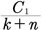
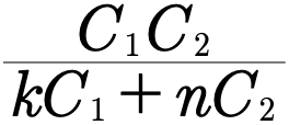
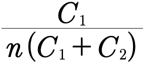
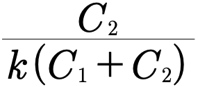
None of the above
Original recorded key: B
Reviewed worked examples
These authored derivations are paired with the original example identities. Added assumptions are stated.
Example 4.2.1 · reviewed solution
Three 2 F capacitors form one lone capacitor in series with a parallel pair. Find Ceq.
Authored clarification: The source’s count says four, but the described network has three; this prompt states the intended described topology.
Combine the parallel pair.
Combine series capacitances.
Invert.
Check
The series equivalent is smaller than the smaller series element.
Example 4.2.2 · reviewed solution
A 3 F capacitor is parallel to two 2 F capacitors in series. The supply is 2 V. Find the voltage on either series capacitor.
Authored clarification: Ideal capacitors; the intermediate conductor is initially neutral.
The series pair has equivalent 1 F.
Its total branch voltage is 2 V.
Both series capacitors carry equal |Q|.
Each series capacitor has 1 V across it.
Check
The two drops add to 2 V; total Ceq=3+1=4 F.
Glossary and deeper reading · 9 refreshers
These editorial refreshers supplement the reading. Definitions and examples are added guidance; original source wording and recorded answers remain in their original context.
-
Capacitor
A capacitor stores energy by separating charge between conducting regions. In the ideal two-plate model, opposite plate charges create a potential difference related to charge by the capacitance. For example, disconnecting a charged capacitor from a battery leaves energy stored until a discharge path is provided.
-
Capacitance
Capacitance is the plate-charge magnitude divided by the potential difference for an ideal capacitor. It is measured in farads and depends on geometry and the material between the conductors. For example, increasing the overlap area of ideal parallel plates increases their capacitance when separation and dielectric stay fixed.
-
Potential difference
Potential difference is the change in electric potential between two locations. It represents electric potential-energy change per unit charge and is measured in volts. For example, the potential difference across a resistor describes the energy transferred per coulomb passing through it.
-
Electric charge
Electric charge is a conserved property that determines electric interactions. It can be positive or negative and is measured in coulombs; ordinary net charges arise from an imbalance of charged particles. For example, transferring electrons between initially neutral objects leaves one negatively charged and the other positively charged.
-
Parallel connection
A parallel connection joins elements across the same two nodes. They therefore have the same potential difference, while their branch currents can differ. For example, two different resistors connected in parallel across a battery generally carry different currents.
-
Equipotential
An equipotential is a set of locations with the same electric potential. Moving a charge along it produces no electric potential-energy change, and electric field vectors are perpendicular to its surface. For example, concentric spherical surfaces around an isolated point charge are equipotentials.
-
Series connection
A series connection places elements along one unbranched path. The same current passes through the series elements, while their potential differences can differ. For example, adding another resistor to a simple series loop raises the total resistance and reduces current from a fixed ideal source.
-
Electromotive force
Electromotive force is energy supplied per unit charge by a source or induction process. Despite its name it is measured in volts, rather than newtons, and can exist even when no current flows. For example, an ideal battery supplies an emf while an induced emf can be produced by changing magnetic flux.
-
Electrical conductor
An electrical conductor contains charge carriers that can move through the material. In electrostatic equilibrium, mobile charges redistribute until the electric field within the conducting material is zero. For example, excess charge on an isolated metal object resides on its surface after the charges settle.