Current and Resistance
Original source retained for reference; this draft does not establish AP coverage.
Original author draft. Original wording and recorded answer states are preserved without claiming reviewed scientific correctness or AP alignment.
Physics 2 original textbook · Chapter 3
Section 4
Section 4
Current and Resistance
Imagine you have an infinite conducting wire and at the ends of this infinite wire there was some potential difference. At negative infinity we will say the potential is +V while at positive infinity we will say the potential is -V. Since there is a potential across this wire this implies that there is some electric field.
In an ordinary resistive metal, negatively charged electrons drift opposite the electric field. Conventional current is defined in the direction of positive charge flow and therefore points along the field. Charge conservation gives .
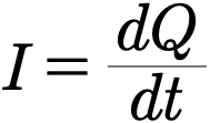
The current is the rate at which charge is moving in the wire. The unit of current is the ampere abbreviated as the amp and is denoted by the symbol A. Using the above definition we say that an amp is equal to one coulomb per second or if we write that down mathematically
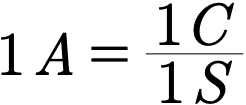
It is important to note that although the electrons are what we consider to be flowing in a conductor the current is almost always defined to be opposite this direction. In this book we will use the convention that the current flows opposite the direction of the electrons so that when a voltage is applied we say that the current moves from the higher voltage to the lower. When working out problems this distinction will not make a difference but it is important to be consistent when talking about certain theorems which will be introduced later.
If we were to view the electrons in the wire previously considered we would notice something quite curious. The electrons instead of exhibiting an orderly march forward would instead be seen to bounce about in a seemingly random way. In fact if we were to track each electrons movement it would be discovered that they were virtually stationary to us and instead each individual electron would be moving very slowly forward. This slow movement of individual electrons is given the name drift velocity, the relatively large current we see only arising from the huge number of electrons flowing together.
Example 3.4.1
A uniform mobile charge density ρ drifts through a wire of area A with velocity v normal to its cross section. Find steady current.
Authored clarification: ρ and v are signed relative to a chosen cross-section normal; neutral background charge does not contribute to drift current.
To begin this problem we must consider the definition of current which has already been laid out.
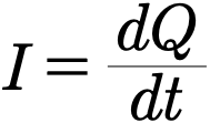
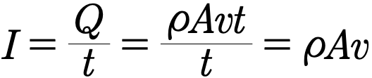
Since we have stipulated that the current is constant the ratio of charge and time is always a constant and we can throw out the differentials. Our new expression for the current is
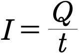
Now we need to find an expression for the charge. To do this we need to consider a wire with charge density ρ, drift velocity v, and cross sectional area A
In a time t a single electron will move a length vt. The volume that this length corresponds to within the wire is then given by the cross sectional area times the length moved. THis gives us that

To get the total charge which has moved through some particular point in a time t we have simply need to multiply ρ with V.

Plugging the above into our definition of the current gives us the desired expression.
Interactive 1.4 Current
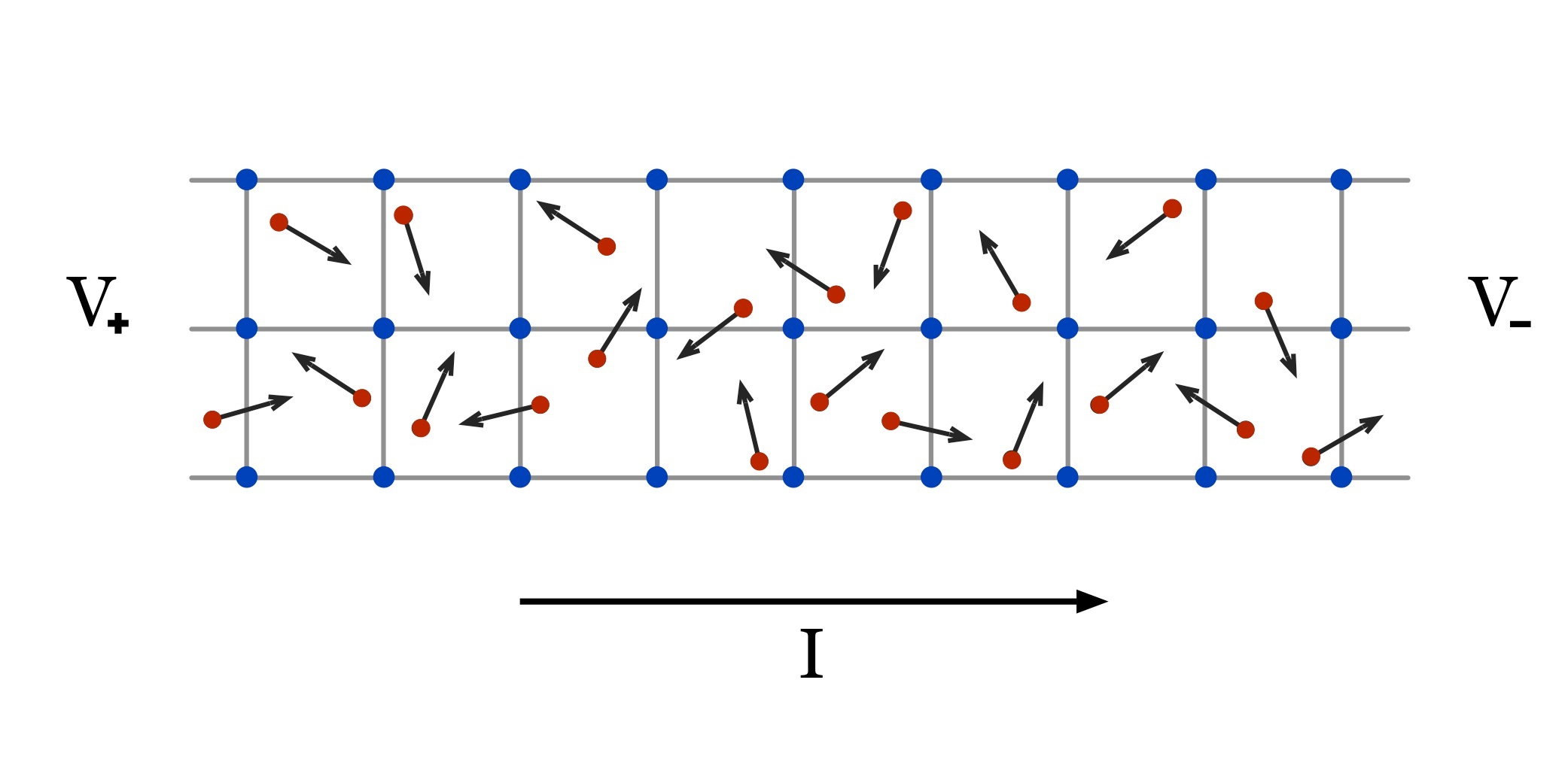
Individual Atoms
Each individual atom as you can see does not necessarily have to be moving in the direction of the current. All that is necessary for a current to exist is a net movement in a particular direction
The Lattice Structure
The lattice represents an arrangement of atoms in solid form. The blue dots are atoms and the grey lines the bombs between them. We take this to be some kind of wire.
Resistance is the tendency of a material to slow the net movement of electrons. In a sense it is very much like frictional coefficient one observes which when having two objects slide together but instead of caused by chemical bonding and other effects is typically being caused by electrons colliding with other particles within the wire.
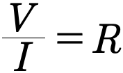
If we assume that for some material its resistance is constant we come to an old, but still useful model for the interrelation between current, voltage, and resistance named Ohm’s Law. It can be stated as follows
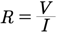
That is that the resistance R is inversely proportional to the current and directly proportional to the voltage. Ohm’s Law is much like the Ideal Gas Law in that only under certain circumstances does it hold.
Ohm’s law applies over an operating range with the conductor’s physical conditions fixed. For many metals, resistance increases with temperature over a moderate range. Semiconductor and other materials can behave differently; temperature dependence must be specified rather than assumed universal.
Although you might consider stopping heat from flowing into the wire this is physically impossible since the very fact that you are running a current through the wire will create heat through the Joule Heating Law.
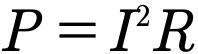
The intuition for this comes from the idea that many molecular collisions are occurring in the wire. By having the electrons flow due to a current we are both increasing the amount and intensity of the collisions occurring which then transfer energy to the surrounding conductor molecules heating up the wire thereby increasing resistance.
Example 3.4.2
Relate Joule heating power to voltage across an ohmic resistor.
Authored clarification: Resistance is fixed over the stated operating conditions.
The goal of this problem is to relate the power P in Joules Heating Law with voltage. To do this we must think about what we have available.
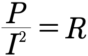
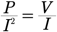
Both Joule’s Heating Law and Ohm’s Law contain the resistance R in them. This gives us a great starting point because if we solve both for R and equate them we will have the wanted variable together.
Solved for R Joule’s Power Law states
Solving Ohm’s Law for R gives us
If we equate the two we then have that
or finally

Gallery 1.4 Heat in a Resistive Media
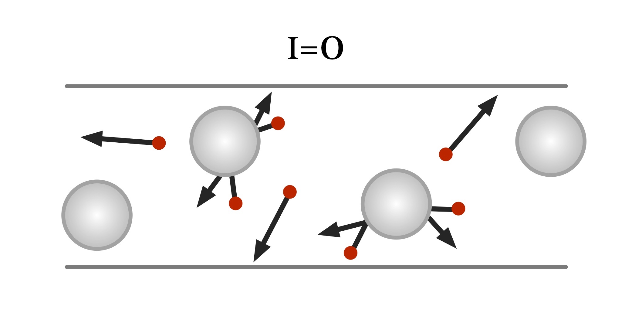
When no current is present the movement of the electrons is due solely to thermal influences. The comparatively large atoms move very little when hit by the electrons due to their relatively low energy.
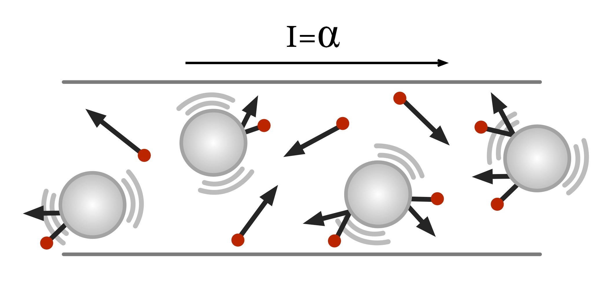
Electric fields do work on mobile charges. Collisions transfer this energy to the material, producing Joule heating at rate . Cooling is a separate transfer of thermal energy to the surroundings; Joule’s law is not a cooling law.
Archived original widget · contains the source error
When no current is present the movement of the electrons is due solely to thermal influences. The comparatively large atoms move very little when hit by the electrons due to their relatively low energy.
After a voltage is applied and a current created the electrons begin colliding with the atoms more and as a result of the voltage have more energy. These electrons now increase the temperature of the system. The temperature of the system is then reduced by the emission of heat given by Joule’s Power Law.
Review 1.4 Current and Resistance
This review preserves the author’s recorded prompts, choices, and answer states. Corrected items have separate reviewed explanations and keys; unchanged draft keys are marked unreviewed. Unfinished items are not scored.
Original question 1
An ohmic component carries 3 mA at 5 V. What is its resistance?
Reviewed answer and reasoning
A
Convert mA to A before R=V/I: 5/0.003=1666.67 Ω.
Authored correction or explicit assumptions; this reviewed key is separate from the archived original recorded states.
Archived original question and recorded key · contains the source error
A piece of wire obeys Ohm’s Law. If the current through the wire is measured at 3 mA and the voltage across the wire is 5 V what is the resistance of the wire?
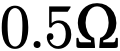

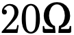
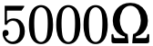
None of the above
Original recorded key: D
Original question 2
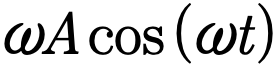
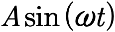
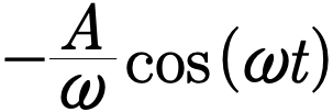
If the charge on an object varies in time by the equation
What is the current flowing into that object?
0
None of the above
Reviewed answer and reasoning
A
I=dQ/dt=A omega cos(omega t), with A here an amplitude of charge, not unit ampere.
The independent semantic audit confirms this source prompt and recorded key under its stated conditions.
Archived original question and recorded key · contains the source error
If the charge on an object varies in time by the equation

What is the current flowing into that object?
0
None of the above
Original recorded key: A
Original question 3
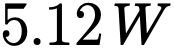
A passive resistive wire carries 8 A with a 100 V potential difference across it, with current entering the higher-potential end. What power is dissipated in the wire?
None of the above
Reviewed answer and reasoning
C
The wire converts electrical energy to heat. With current entering the higher-potential end, the dissipated power is P=IΔV=(8 A)(100 V)=800 W. The circuit’s source supplies this energy; the passive wire dissipates it.
The prompt uses the passive sign convention, so the calculated power is energy transferred into the wire.
Archived original question and recorded key · contains the source error
A wire has a current of 8 A and voltage of 100 V. Determine the power which is produced by the wire.



None of the above
Original recorded key: C
Original question 4
Resistance depends on temperature.
True
False
Reviewed answer and reasoning
A
Resistance can depend on temperature.
The independent semantic audit confirms this source prompt and recorded key under its stated conditions.
Archived original question and recorded key · contains the source error
Resistance depends on temperature.
True
False
Original recorded key: A
Original question 5
Under fixed geometry, material, and temperature, an ohmic resistor has V proportional to I. What relation expresses this?
Every component always obeys V=IR
Reviewed answer and reasoning
A
Ohm’s law is an operating model for an ohmic component. Nonohmic devices and changing temperature need separate descriptions.
This reviewed version states the assumptions or convention needed for one determinate answer. The archived source prompt and key are retained.
Archived original question and recorded key · contains the source error
In Ohm’s Law resistance is assumed to be constant.
True
False
Original recorded key: A
Chapter 3 Problems
An isolated spherical metal conductor of radius R carries total charge Q at electrostatic equilibrium. Find E and V inside and outside using V(∞)=0.
Authored clarification: No external fields are present. The sphere’s symmetry gives uniform surface charge.
Optional original-source extension. Prerequisites: infinite-sheet superposition and conductor electrostatic equilibrium. This item makes no AP coverage claim.
A thin infinite insulating sheet at z=0 has uniform surface density σ. Two neutral, isolated conducting slabs are placed symmetrically, one on either side. Determine the field in the vacuum gaps adjacent to the insulating sheet.
Authored clarification: The source does not specify finite versus infinite geometry, grounding, net slab charge or sheet density. This symmetric infinite-sheet model fixes those conditions; a different electrical connection can change the answer.
Four identical 2 mF parallel-plate capacitor units are electrically combined in parallel. Find their total capacitance.
Authored clarification: Merely placing capacitors next to one another does not specify a circuit. Here their corresponding terminals are connected in parallel; different connections give different results.
Optional original-source extension. Prerequisites: the ideal parallel-plate model and the meaning of an unconstrained maximum. This item makes no AP coverage claim.
A capacitor must fit inside a cube of side L. Does this alone determine which geometry—parallel plate, coaxial cylinder or concentric spheres—has the greatest capacitance?
Authored clarification: No minimum electrode spacing, dielectric, conductor thickness or breakdown limit was supplied. The task is to diagnose whether a maximum is defined.
Optional original-source extension. Prerequisites: series and parallel capacitance for two distinct dielectric layouts. This item makes no AP coverage claim.
An air-filled parallel-plate capacitor has C₀=1 F. A dielectric K=4 fills (a) one quarter of plate area through the full gap, or (b) one quarter of gap thickness over the entire area. Find C for both, neglecting fringing.
Authored clarification: The original “fourth” is ambiguous. Both physically distinct layouts are solved explicitly.
A vacuum parallel-plate capacitor has plate area A, separation d and charges ±Q. Derive its electric energy density in terms of Q, A and ε₀, neglecting fringing.
Authored clarification: Energy density refers to the nearly uniform gap field, and A is one plate’s facing area.
Optional original-source extension. Prerequisites: long-wire magnetic fields and force on a current-carrying wire. This item makes no AP coverage claim.
Two long parallel wires separated by distance s carry equal maintained currents I in opposite directions. They remain electrically insulated. Describe their interaction and give the magnetic force per unit length.
Authored clarification: The original does not say whether wires are electrically joined or merely placed adjacent. This problem supplies two distinct insulated long wires; joining them would require a circuit specification.
At constant 20 V, a circuit’s total resistance increases from 1 Ω to 10 Ω. Find its initial and final Joule power and the final-to-initial ratio.
Authored clarification: The ideal source holds the voltage at 20 V while the total resistance changes. The reviewed wording asks for both powers and their ratio.
Reviewed worked examples
These authored derivations are paired with the original example identities. Added assumptions are stated.
Example 3.4.1 · reviewed solution
A uniform mobile charge density ρ drifts through a wire of area A with velocity v normal to its cross section. Find steady current.
Authored clarification: ρ and v are signed relative to a chosen cross-section normal; neutral background charge does not contribute to drift current.
Count swept volume in Δt.
Multiply by signed mobile charge density.
Divide by time.
Check
For electrons both ρ and their drift component can be negative, yielding positive conventional current.
Example 3.4.2 · reviewed solution
Relate Joule heating power to voltage across an ohmic resistor.
Authored clarification: Resistance is fixed over the stated operating conditions.
Electrical power is current times voltage.
Use Ohm’s law.
Substitute.
Check
At fixed V, larger total R means less total power.
Glossary and deeper reading · 8 refreshers
These editorial refreshers supplement the reading. Definitions and examples are added guidance; original source wording and recorded answers remain in their original context.
-
Electrical resistance
Electrical resistance relates the potential difference across an element to the current through it. It is measured in ohms and depends on the element’s material, geometry, and conditions. For example, a longer uniform wire has greater resistance when cross-sectional area and material remain fixed.
-
Potential difference
Potential difference is the change in electric potential between two locations. It represents electric potential-energy change per unit charge and is measured in volts. For example, the potential difference across a resistor describes the energy transferred per coulomb passing through it.
-
Electric field
An electric field assigns the electric force per unit positive test charge to each location. The field is produced by the sources and is a vector, while the force on a negative charge points opposite the field. For example, the electric field between ideal parallel capacitor plates can accelerate an electron opposite the field arrows.
-
Conventional current
Conventional current points in the direction that positive charge would move through a circuit. In a metal wire, electrons usually drift in the opposite direction. For example, a current arrow pointing right in a metal wire does not mean the conduction electrons drift right.
-
Electric charge
Electric charge is a conserved property that determines electric interactions. It can be positive or negative and is measured in coulombs; ordinary net charges arise from an imbalance of charged particles. For example, transferring electrons between initially neutral objects leaves one negatively charged and the other positively charged.
-
Electric current
Electric current is the net rate of charge flow through a specified cross section. It is measured in amperes, or coulombs per second, with direction defined by positive-charge motion. For example, the same steady current passes through each element of a simple unbranched series loop.
-
Electrical conductor
An electrical conductor contains charge carriers that can move through the material. In electrostatic equilibrium, mobile charges redistribute until the electric field within the conducting material is zero. For example, excess charge on an isolated metal object resides on its surface after the charges settle.
-
Drift velocity
Drift velocity is the small average carrier velocity associated with net charge flow in a conductor. It is distinct from the carriers’ random microscopic motion and from the speed at which a circuit’s electromagnetic changes propagate. For example, electrons can drift slowly along a wire while a circuit responds rapidly when a switch closes.