Resistors in Circuits
Original source retained for reference; this draft does not establish AP coverage.
Original author draft. Original wording and recorded answer states are preserved without claiming reviewed scientific correctness or AP alignment.
Physics 2 original textbook · Chapter 4
Section 3
Resistors in Circuits
As you recall in a parallel connection the circuit elements are placed side by side so that each element in a parallel connection connects to the same node. Like in the case of capacitors the voltage across each resistor in parallel must be the same. This happens as a result of the wire being a conducting medium which touches one side of every resistor. The fact that the wire is a conducting medium forces the potential of a single piece of wire to be the same. Since the resistors essentially cut the wire into two sides each side of each resistor has two differing potentials and because like sides are connected in a parallel connection all these potentials are alike in each resistor so that the voltages across them are the same. This consideration gives us the following relation involving voltages.

The next thing we need to consider is the current running through the resistors. This is a little more tricky. As the current flows through a particular node it splits into multiple wires. Eventually when the wires again meet at a new node the flows will merge again. Since charge is conserved we would expect there to be no difference in the beginning and ending currents. Therefore we expect the beginning current to be the sum of the split currents giving us the following equation.
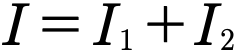
The final piece of this puzzle is to use what we know about resistors and resistance to determine how connecting resistors in parallel effects the overall resistance of a circuit. Recall that Ohm’s law is given by
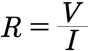
If we solves for I in Ohm’s Law and then substitute for I in our current equation recalling that the voltages are all the same we can get something useful.

By dividing the voltage out we can then get our desired equation relating resistances.
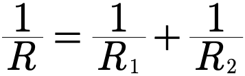
Which like the capacitor equation can be put into a slightly more useful form.
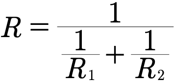
Gallery 1.8 Resistors in Parallel
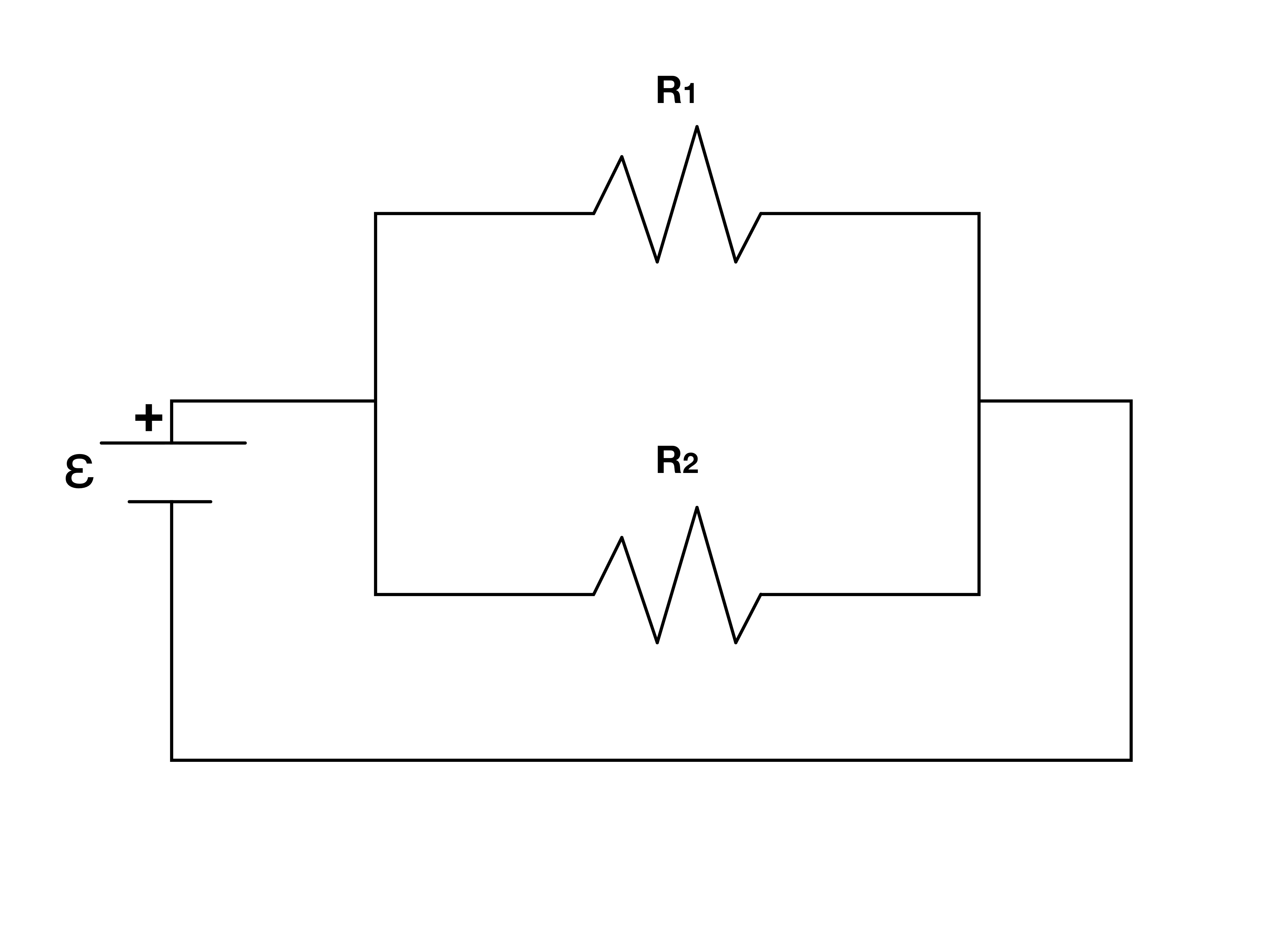
As with capacitors a parallel connection refers to elements being “side-by-side”.
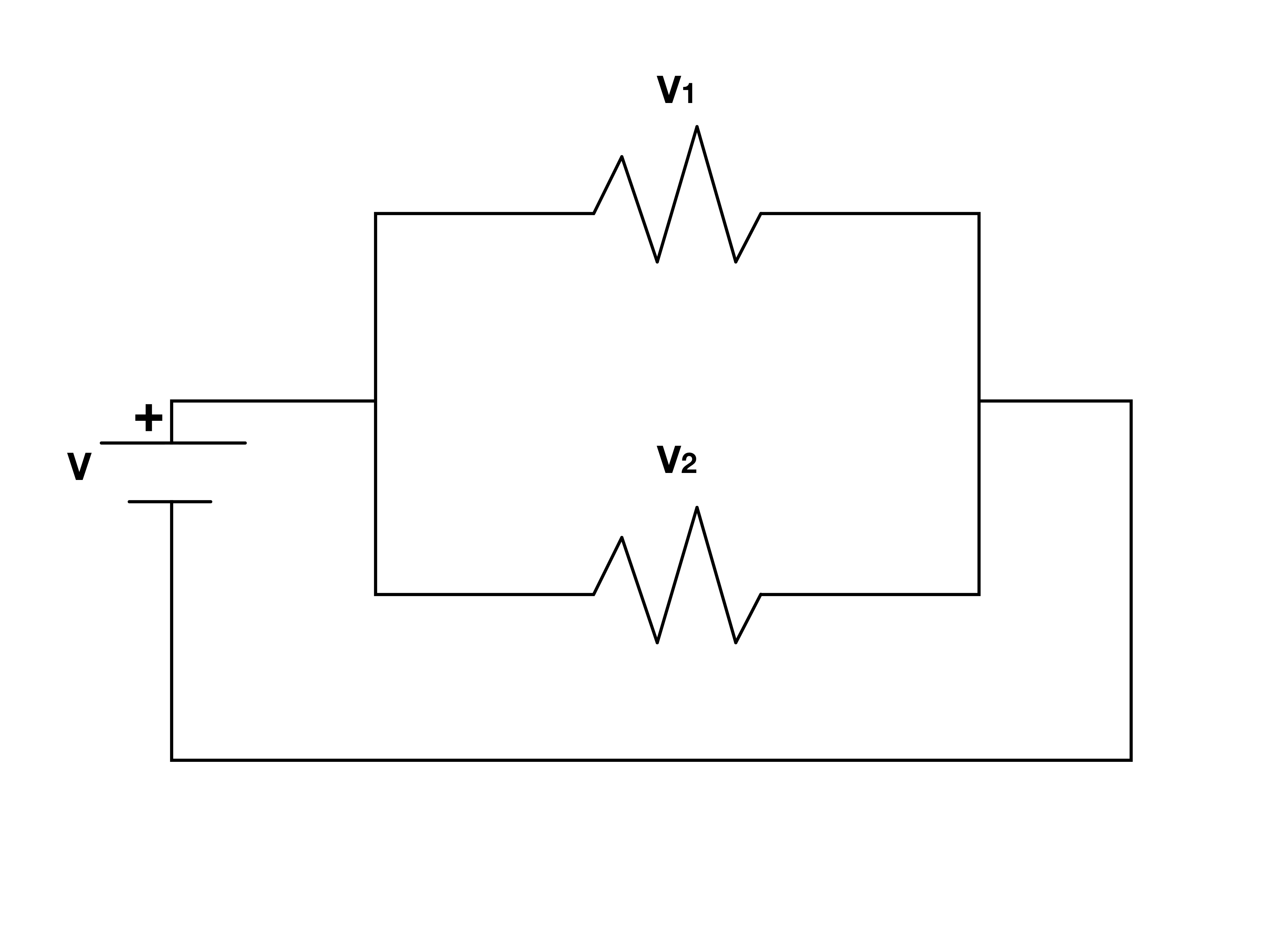
Perfect conductors keep constant potentials. Like in capacitors this fact leads to each element in a parallel connection holding the same voltage.
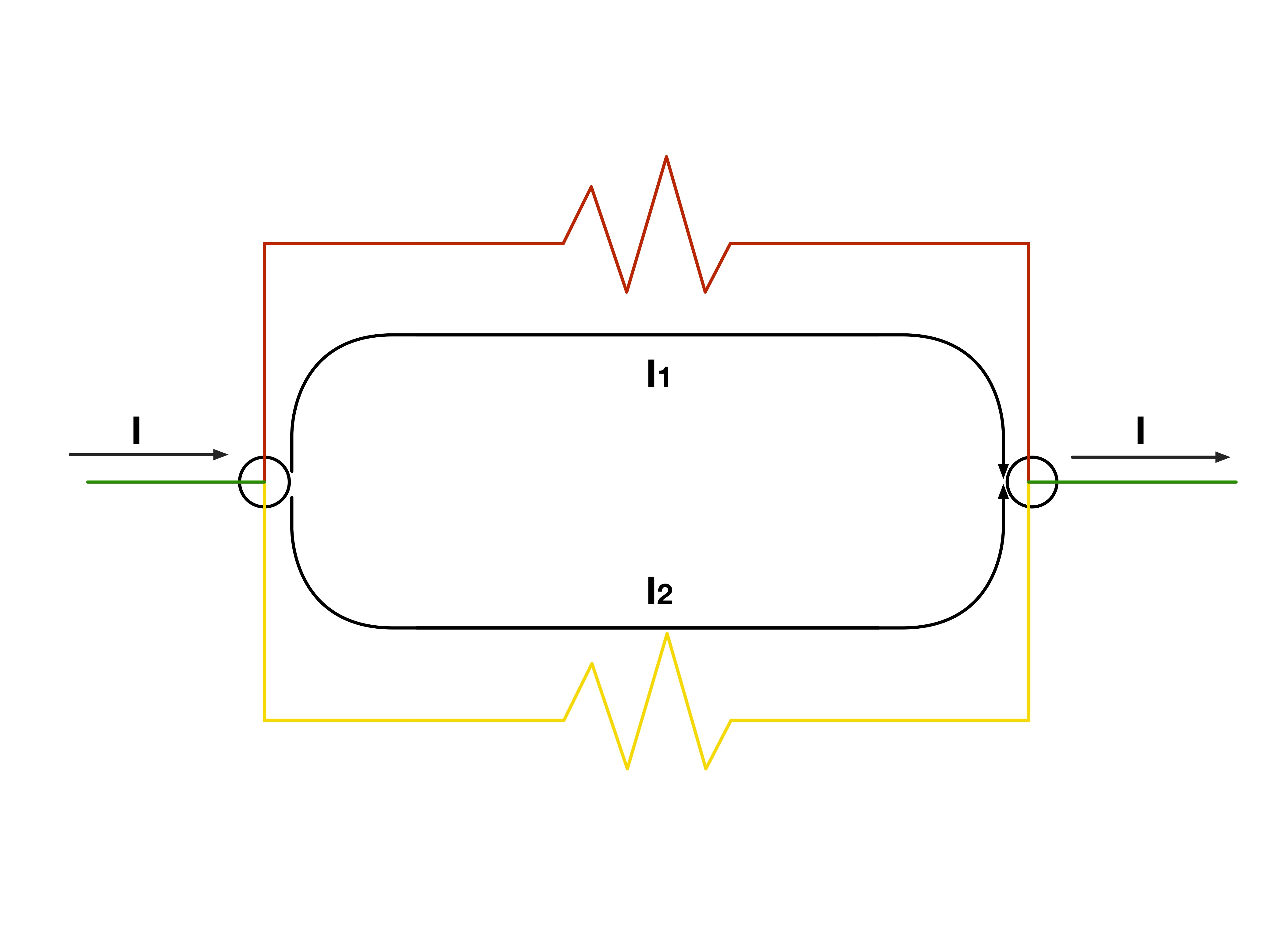
Current is nothing more than moving charge. As a result the conservation applies to current just as must as it applies to charge. The sum of the currents in each section of wire must then equal the total incoming and outgoing currents.
We will now look at resistors in a series connection. Recall that the series connection is when you place an electronic component back to back.
We will again begin by looking at the voltage. If we were to use only two resistors and an emf we would divide the circuit into three sections. We will say that the first section is at a potential P₊, the second a potential P, and the third P₋. Using these potentials it is possible to derive a relationship between the voltages of the resistors.
The voltage across both resistors is given by

If we both add and subtract P in this equation we then get

Now all we need is to notice that the voltages across each of the resistors is nothing more than

and

Which when substituted into the equation for V gives us a relationship of the voltages between the different elements.

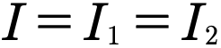
Current for resistors in series is a little easier to describe than the parallel connection. This is because for capacitors in series there are no splits in the circuit which would divide the current. As a result of this lack of splits the current running through both resistors will be the same as the total incoming currents. We can writ this down mathematically with the following equation.
Now we have everything we need to find an expression for the resistance for resistors in series. Consider the equation we found for the voltage.

If we solve ohms law for voltage and make the appropriate substitutions we get that

Since
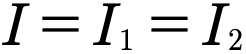
We get that

Which after dividing through by I leads us to our long sought after equation

Gallery 1.9 Resistors in Series
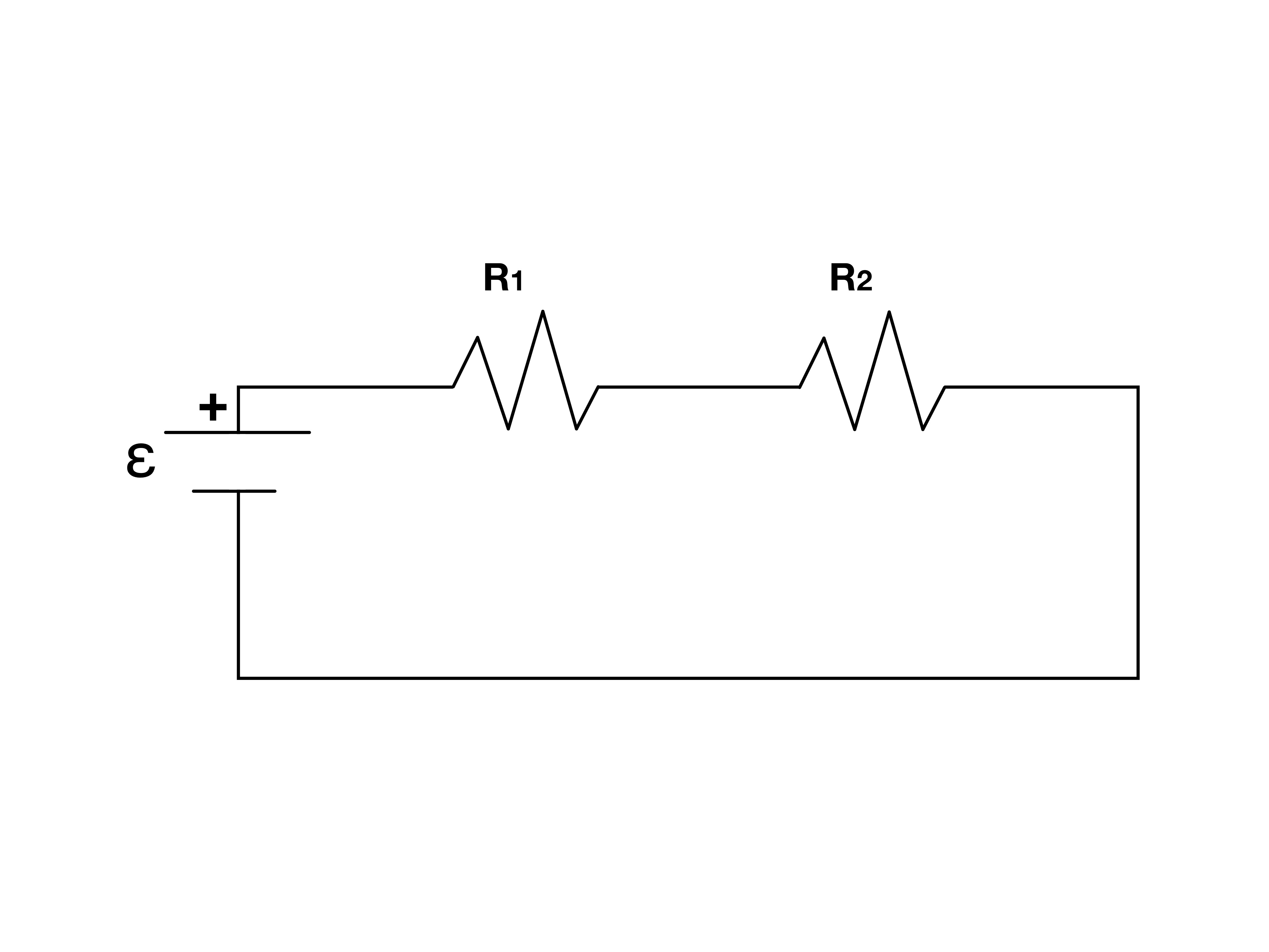
Series connections refer to circuit elements being placed “back-to-back” as above.
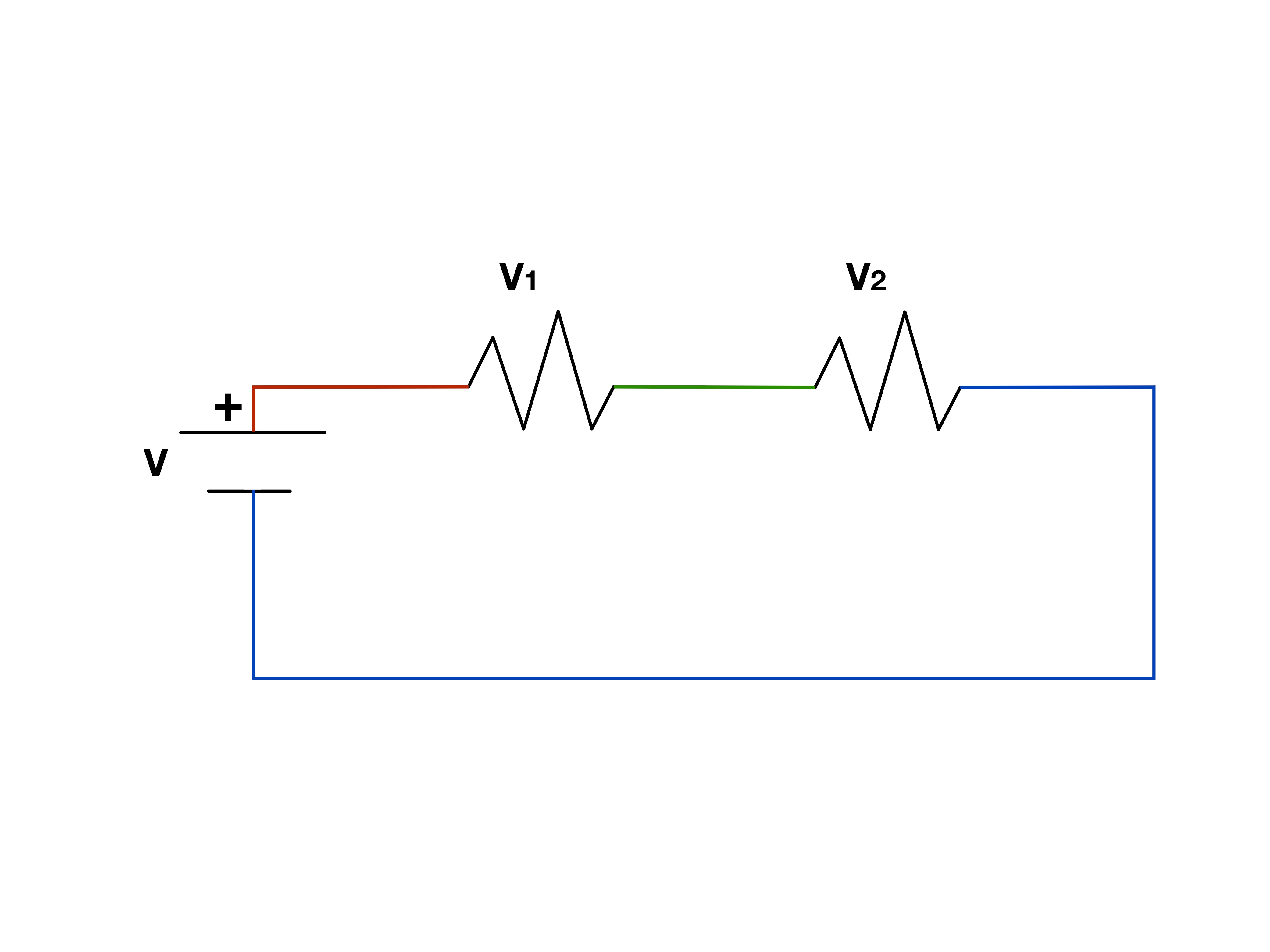
Each section of wire is held at a constant potential if we assume it is a perfect conductor. Since the emf provides potential to the entire circuit the sum of voltages across each circuit element must equal the emfs voltage.
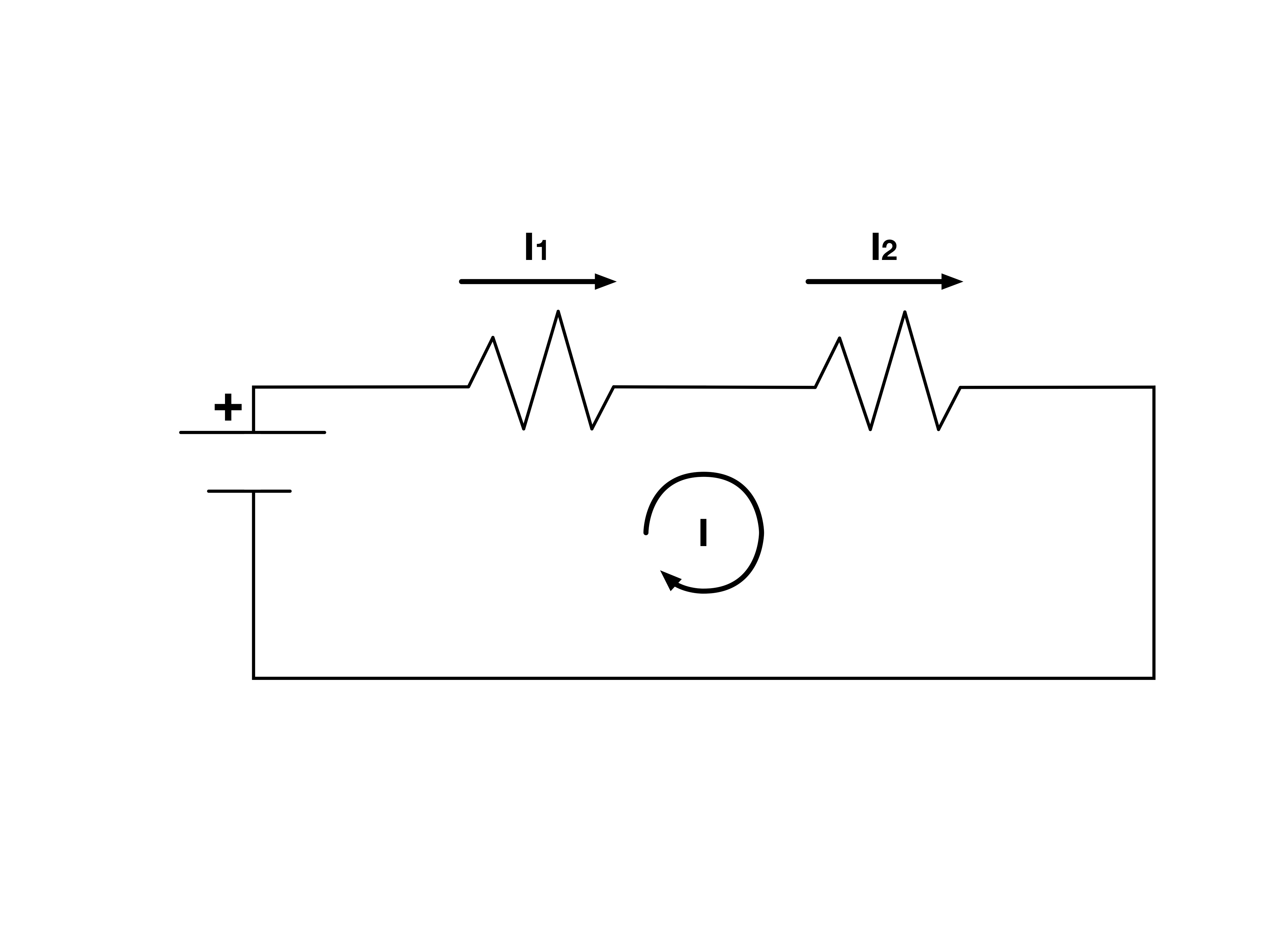
Current as you may recall is essentially the rate of flow of charge. When charge is flowing inside a wire we can think of it as water in a pipe. The flow through pipe is a constant value dictated by the bottleneck. Current through a wire can be though of in a similar way.
Example 4.3.1
Two 16 Ω resistors in parallel are in series with three 6 Ω resistors in parallel. Find total R.
Authored clarification: All components are ohmic and ideal wires have negligible resistance.
To determine the total resistance of this network we will first consider the parallel resistor sets alone then consider what happens to them when in series.
As we have figured out when resistors are placed in parallel they obey the following equation.
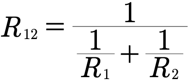
Since in our case the resistors both have the same resistance this equation can be slightly reduced.
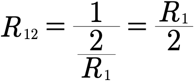
Plugging in the appropriate value for the resistance gives us that
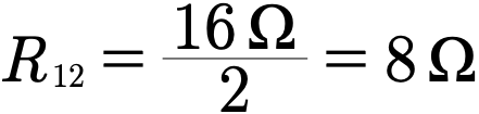
The second parallel set behaves much in the same way. Since we have three resistors each with the same resistance in parallel we have that

Or, after plugging in the appropriate resistance
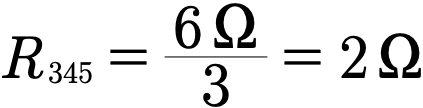
Finally we an consider the two parallel resistor sets as in series. To determine the capacitance of the two sets in series we will use the equation for resistors in series so that

Example 4.3.2
Two parallel 20 Ω resistors are in series with three parallel 60 Ω resistors across 3 V. Find voltage on the first group.
Authored clarification: No additional resistance in source or wires.
Let’s begin by giving some names to the resistors of each set. The total resistance of the circuit will be denoted by

The resistance of the resistors in the first and second set respectively will be denoted by
 ,

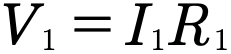
Now that we’re set we can begin looking at the problem. Recall that for a particular resistor voltage, current, and resistance are related through Ohm’s Law which is stated as follows.

For each resistor in the first set we then have
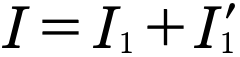
Now remember that for resistors in parallel current is additive. That is the sum of the currents through each resistor must equal the total incoming current. In this case the total incoming current is the circuits total current. As an equation we can state this as
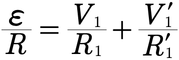
If we now use Ohm’s Law to substitute in for the current of each resistor we get that
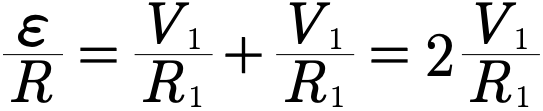
Since both the voltages and the resistances are the same for each parallel resistor the above may be simplified.
Solving for the appropriate in terms of knowns then gives us
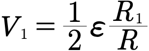
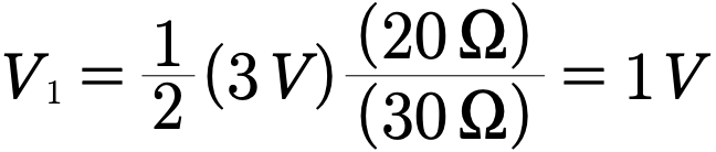
Which after plugging in numerical values gives us our answer.
Review 1.3 Resistors in Circuits
This review preserves the author’s recorded prompts, choices, and answer states. Corrected items have separate reviewed explanations and keys; unchanged draft keys are marked unreviewed. Unfinished items are not scored.
Original question 1
In a quasistatic circuit with negligible charge accumulation, is current the same along one unbranched wire segment?
Yes
No
Reviewed answer and reasoning
A
Charge conservation gives the same current entering and leaving each small segment under negligible accumulation.
This reviewed version states the assumptions or convention needed for one determinate answer. The archived source prompt and key are retained.
Archived original question and recorded key · contains the source error
A wire with no nodes has the same current throughout.
True
False
Original recorded key: A
Original question 2
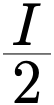
Two sets of three parallel resistors are in series. The resistors have the same resistance. what is the current of the wire connecting the two sets if the total current were I?
None of the above
Reviewed answer and reasoning
B
The joining series wire carries total I before next split, not I/3.
The independent semantic audit confirms this source prompt and recorded key under its stated conditions.
Archived original question and recorded key · contains the source error
Two sets of three parallel resistors are in series. The resistors have the same resistance. what is the current of the wire connecting the two sets if the total current were I?


None of the above
Original recorded key: B
Original question 3
Resistors of resistance 1 Ω, 3 Ω, and 5 Ω are placed in series. What is the total total resistance of the network to two decimal places?
0.65 Ω
2.88 Ω
5.75 Ω
9.00 Ω
None of the above
Reviewed answer and reasoning
D
Series sum 1+3+5=9.00 ohm.
The independent semantic audit confirms this source prompt and recorded key under its stated conditions.
Archived original question and recorded key · contains the source error
Resistors of resistance 1 Ω, 3 Ω, and 5 Ω are placed in series. What is the total total resistance of the network to two decimal places?
0.65 Ω
2.88 Ω
5.75 Ω
9.00 Ω
None of the above
Original recorded key: D
Original question 4
Three resistors with resistances of 1 Ω, 2 Ω, and 3 Ω are placed in parallel. What is the total resistance of the network to two decimal places?
0.55 Ω
2.20 Ω
3.67 Ω
6.00 Ω
None of the above
Reviewed answer and reasoning
A
Parallel inverse sum gives 6/11=.54545 ohm, rounds .55 ohm.
The independent semantic audit confirms this source prompt and recorded key under its stated conditions.
Archived original question and recorded key · contains the source error
Three resistors with resistances of 1 Ω, 2 Ω, and 3 Ω are placed in parallel. What is the total resistance of the network to two decimal places?
0.55 Ω
2.20 Ω
3.67 Ω
6.00 Ω
None of the above
Original recorded key: A
Original question 5
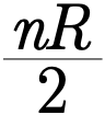
A network is composed of two parallel sets of n resistors in series. What expression describes the networks total resistance if all resistors have resistance R?
None of the above
Reviewed answer and reasoning
D
Each n-parallel group has R/n. Two such groups in series have 2R/n.
Reviewed correction. Archived source choices and key remain readable.
Archived original question and recorded key · contains the source error
A network is composed of two parallel sets of n resistors in series. What expression describes the networks total resistance if all resistors have resistance R?


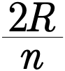
None of the above
Original recorded key: C
Gallery 1.10 Example 4.3.1 and 4.3.2
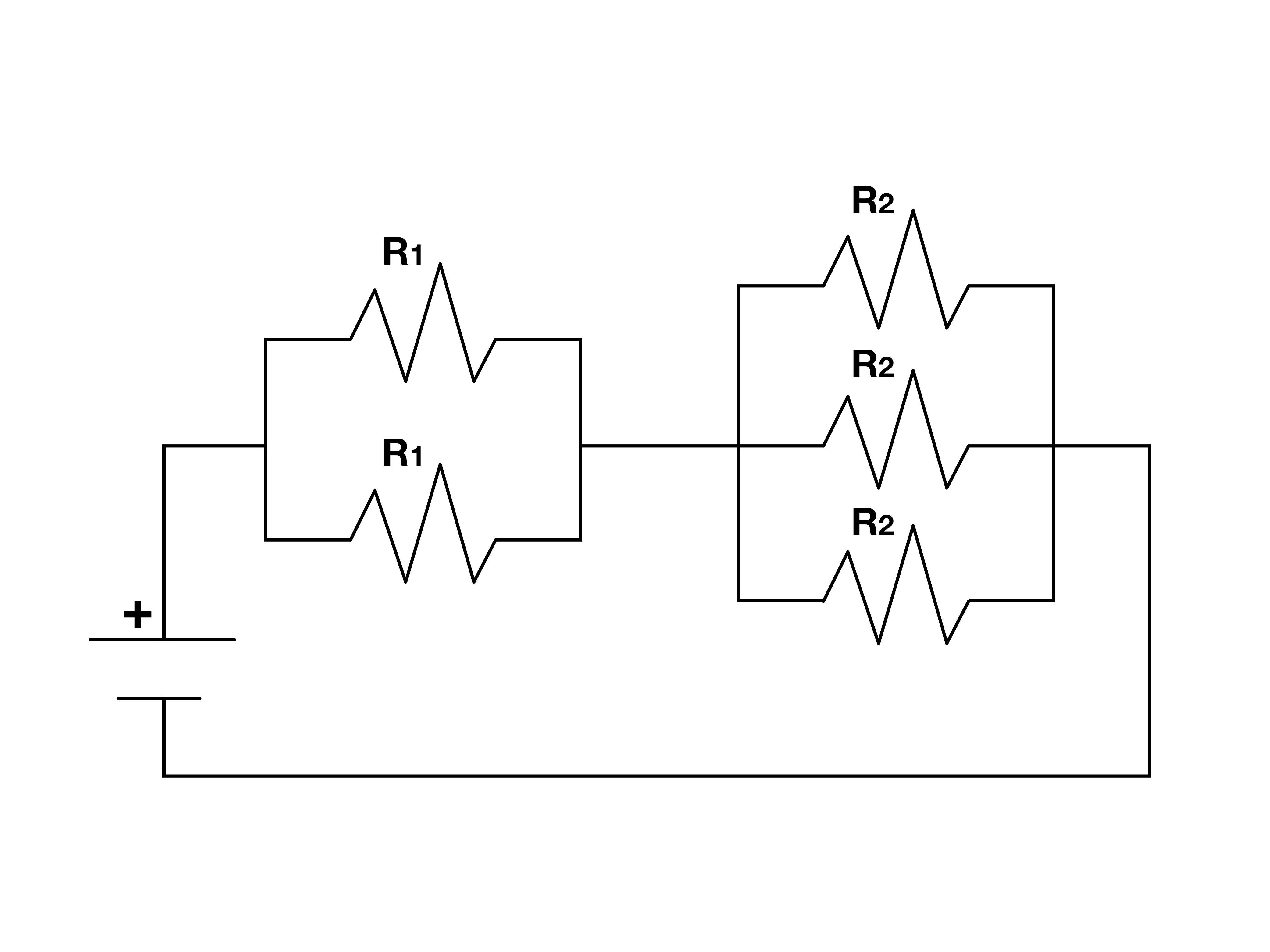
This is the circuit diagram to be used with Examples 4.3.1 and 4.3.2.
Reviewed worked examples
These authored derivations are paired with the original example identities. Added assumptions are stated.
Example 4.3.1 · reviewed solution
Two 16 Ω resistors in parallel are in series with three 6 Ω resistors in parallel. Find total R.
Authored clarification: All components are ohmic and ideal wires have negligible resistance.
Combine first group.
Combine second group.
Add series groups.
Check
Each parallel group is smaller than one constituent resistor.
Example 4.3.2 · reviewed solution
Two parallel 20 Ω resistors are in series with three parallel 60 Ω resistors across 3 V. Find voltage on the first group.
Authored clarification: No additional resistance in source or wires.
Combine groups.
Find series current.
Use the first group’s equivalent resistance.
The first parallel group has 1 V across it.
Check
The second drop is 2 V; together they equal the source voltage.
Glossary and deeper reading · 9 refreshers
These editorial refreshers supplement the reading. Definitions and examples are added guidance; original source wording and recorded answers remain in their original context.
-
Parallel connection
A parallel connection joins elements across the same two nodes. They therefore have the same potential difference, while their branch currents can differ. For example, two different resistors connected in parallel across a battery generally carry different currents.
-
Capacitor
A capacitor stores energy by separating charge between conducting regions. In the ideal two-plate model, opposite plate charges create a potential difference related to charge by the capacitance. For example, disconnecting a charged capacitor from a battery leaves energy stored until a discharge path is provided.
-
Electric current
Electric current is the net rate of charge flow through a specified cross section. It is measured in amperes, or coulombs per second, with direction defined by positive-charge motion. For example, the same steady current passes through each element of a simple unbranched series loop.
-
Electric charge
Electric charge is a conserved property that determines electric interactions. It can be positive or negative and is measured in coulombs; ordinary net charges arise from an imbalance of charged particles. For example, transferring electrons between initially neutral objects leaves one negatively charged and the other positively charged.
-
Electrical resistance
Electrical resistance relates the potential difference across an element to the current through it. It is measured in ohms and depends on the element’s material, geometry, and conditions. For example, a longer uniform wire has greater resistance when cross-sectional area and material remain fixed.
-
Ohm’s law
Ohm’s law describes an element whose current is proportional to its potential difference under the stated conditions. Such an element has constant resistance over the modeled range, giving a straight-line current–voltage relationship through the origin. For example, a fixed-temperature ideal resistor follows this model, whereas a warming filament bulb need not.
-
Potential difference
Potential difference is the change in electric potential between two locations. It represents electric potential-energy change per unit charge and is measured in volts. For example, the potential difference across a resistor describes the energy transferred per coulomb passing through it.
-
Series connection
A series connection places elements along one unbranched path. The same current passes through the series elements, while their potential differences can differ. For example, adding another resistor to a simple series loop raises the total resistance and reduces current from a fixed ideal source.
-
Electromotive force
Electromotive force is energy supplied per unit charge by a source or induction process. Despite its name it is measured in volts, rather than newtons, and can exist even when no current flows. For example, an ideal battery supplies an emf while an induced emf can be produced by changing magnetic flux.