Forces and Free-Body Diagrams
Draw the actual interactions on one object and write component equations.
The arrow has to come from somewhere
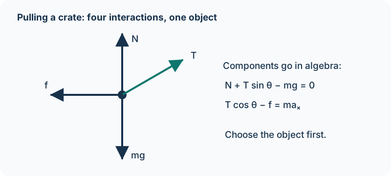
Say you’re pulling a crate across the floor with a rope. The crate has a gravitational interaction with Earth, a contact interaction with the floor, and a contact interaction with the rope. Those interactions—not the direction you hope the crate will move—tell us what belongs on its free-body diagram.
A force is a vector describing an interaction between objects or systems. Every force on the crate has another object as its source. The crate doesn’t exert a net force on itself. Contact forces arise from microscopic electric interactions among atoms at the contacting surfaces. AP Physics 1 uses their macroscopic normal, friction, spring, and tension models; it doesn’t ask us to calculate those atomic interactions.
A free-body diagram, or FBD, isolates one chosen object or system and shows the forces exerted by its environment. Start with a dot representing its center of mass. Draw each actual force as an individual straight arrow starting at that dot, pointing in the force’s direction. Label arrows by type and, when needed, by source: F_Earth on crate, for instance.
What doesn’t go on the diagram?
Don’t draw velocity or acceleration as force arrows. You may show them separately beside the diagram, clearly labeled as motion information. Don’t add an extra “net force” arrow along with all the forces; net force is their sum. And don’t include the force the crate exerts on the rope in the crate’s FBD—that force belongs to the rope’s diagram.
The supplied CED also asks students to draw individual forces, not their components, on exam free-body diagrams. Resolve components in your algebra or on a separate construction. Drawing both mg downward and mg sin θ downhill as if they were separate forces double-counts gravity. If two actual forces point in the same direction, draw their arrows side by side rather than overlapping.
Choose coordinates that make the equations simple. For an incline, use x parallel to the surface and y perpendicular to it. The normal force lies along positive y, while gravity is still vertically downward. Relative to those axes, gravity has components mg sin θ downhill and mg cos θ into the surface. Rotating axes cannot rotate the physical force.
Example 2.2.1 — Pulling at an angle
A 2 kg crate rests on a level floor while a rope pulls 30° above horizontal with tension 10 N. Use g = 10 m/s². The forces are gravity 20 N downward, normal force upward, rope tension up and right, and possibly friction along the surface. Vertical acceleration is zero, so N + T sin 30° − mg = 0. Thus N = 20 − 5 = 15 N.
Notice that N isn’t automatically mg. The rope helps support the crate. Its horizontal component is T cos 30° ≈ 8.66 N. If the crate is stationary, static friction must supply an equal leftward force, provided the surface can support it. If it slides, the kinetic-friction model and Newton’s second law determine acceleration. The picture alone doesn’t tell us which friction condition applies.
Build the equations from the picture
On a frictionless 30° incline, a 2 kg block has only gravity and the normal force. Perpendicular balance gives N = mg cos 30° ≈ 17.3 N. Along the slope, the net force is mg sin 30° = 10 N downhill. The components are useful calculations, but there are still only two actual force arrows on the FBD.
As a quick experiment, place a force sensor under a stationary object and pull gently upward at different angles with a spring scale. Record tension, angle, and the sensor reading. Predict N = mg − T sin θ and compare the trend. Keep contact with the platform; once it loses contact, N is zero and the model changes. A careful procedure names the measured angle and holds mass fixed, rather than simply promising to “measure the forces.”
Example 2.2.2 — An internal push cannot propel the whole cart
A person stands inside a cart on a frictionless horizontal track and pushes its front wall. For the person-plus-cart system, person-on-wall and wall-on-person are internal equal-and-opposite forces, so their horizontal vector sum is zero. The person and cart may move relative to one another, but the system cannot exert a net force on itself or accelerate its center of mass by that internal push. An external interaction, such as pushing on the ground, is needed to change the system’s total horizontal motion.
A hand pushing a wall, the floor’s normal force, and friction between shoes and a floor are contact interactions: the objects touch and their atoms interact electrically. These microscopic interatomic electric forces produce the macroscopic contact-force models. Gravity between Earth and the person is a distinct interaction at a distance. We identify the electric origin of contact forces without calculating atomic electric forces in AP Physics 1.
If an external 6 N pull acts rightward on the 3 kg person-plus-cart system while internal pushes are 20 N and 20 N opposite, the system force sum is 6 + 20 − 20 = 6 N rightward and its center-of-mass acceleration is 2 m/s². On a whole-system FBD draw only the external pull and the balancing vertical interactions. Internal pairs belong in diagrams of the constituent objects, not as extra whole-system force arrows.
Check what you know
Pause & try it
Let's see what stuck.
Choose an answer, then check the reasoning. Try the written problems below before opening their solutions.
0 of 3 checked · 0 correct
Give it a try
Practice 1
Draw an FBD for a book pushed horizontally against a vertical wall and held stationary. Identify the source and direction of every force.
Practice 2
A 3 kg block rests on a horizontal floor. A downward push of 8 N is added. Find N using g = 10 m/s² and explain why it differs from weight.
Practice 3
For a block sliding down a rough incline, choose useful axes, draw only actual forces, then write both component equations without assuming constant speed.
Keep exploring
The original Newton’s Laws and FBDs and Force Analysis keep their worked examples and quizzes. Apply the exam drawing conventions here when using them.
Course scope and standards: the supplied AP Physics 1 CED, printed pages 44, 45; Topic 2.2 and its exact learning objectives. The official College Board CED is the public source; the project audit records the supplied edition.
Supporting physics references: OpenStax: the force concept; OpenStax: normal and tension forces. These lessons, diagrams, examples, and practice questions were written for this book.
Explain and apply the model
Try these problems before opening the solutions. State your assumptions, show the diagram or calculation, and explain what makes your answer follow.
Find the source of every push
A person sits in a wheeled cart on a horizontal frictionless track and pushes the cart’s front wall. Choose person plus cart as the system. Later a rope outside the system pulls it rightward with 6 N. Total mass is 3 kg and there is no vertical acceleration. Use g = 10 m/s².
(a) Explain why the person’s internal push cannot exert a net force on the person-plus-cart system or change its center-of-mass motion by itself. Identify the two recipient objects for the internal force pair and explain why relative motion is still possible.
(b) Explain the microscopic physical origin of the person–wall push and the track’s normal contact force. State why these are contact interactions and why their electric origin does not make them additional electric-force arrows on a macroscopic free-body diagram.
(c) Draw the whole-system free-body diagram after the rope is attached, with each actual external force as a straight arrow from the dot. Identify every source and direction, exclude internal forces, and calculate the horizontal center-of-mass acceleration.
Your written working
Drawing is temporarily unavailable. Work on paper if needed, then record your reasoning here.
Saving written working requires JavaScript. The problem remains available above; keep your work on paper or in your own notes.
Glossary and deeper reading · 12 refreshers
These editorial refreshers supplement the reading. Definitions and examples are added guidance; original source wording and recorded answers remain in their original context.
-
Force
A force describes an interaction that can change an object’s momentum. It is a vector measured in newtons, so both size and direction matter when forces are added. For example, a rope can pull a cart while the floor exerts friction in another direction.
-
Vector
A vector is a quantity with a magnitude and a direction, represented by an arrow or by components along chosen axes. Vectors add by adding corresponding components rather than simply adding their magnitudes. For example, an eastward displacement followed by a northward displacement produces a resultant pointing northeast. The zero vector has zero magnitude and no unique direction.
-
Center of mass
The center of mass is the position obtained by weighting each part’s position by its mass. Its motion represents the translational motion of the whole system under the net external force. For example, adding a heavy object to one end of a light bar shifts the center of mass toward that end.
-
Velocity
Velocity describes how position changes with time and includes direction. Instantaneous velocity describes one moment, while average velocity is displacement divided by elapsed time. For example, a car turning a corner can change velocity while maintaining the same speed.
-
Acceleration
Acceleration is the vector rate of change of velocity with time. It can change an object’s speed, direction, or both, and it is measured in meters per second squared. For example, a satellite moving at constant speed in a circular orbit accelerates toward the center.
-
Gravity
Gravity is the attractive interaction between masses in the Newtonian model. For spherical bodies or point-mass approximations, its strength decreases with the square of the separation between their centers. For example, Earth’s gravity provides the inward force that keeps a satellite in orbit.
-
Normal force
A normal force is a contact force perpendicular to the local surface of contact. Its magnitude is set by the motion and the other forces, so it need not equal the object’s weight. For example, a wall’s normal force on a leaning ladder points horizontally rather than upward.
-
Vector component
A vector component describes the part of a vector along a chosen axis. Its signed value changes when the axes change, even though the physical vector remains the same. For example, a diagonal launch velocity can be resolved into horizontal and vertical components that share the same elapsed time.
-
Net force
Net force is the vector sum of all forces acting on the object or system under consideration. For constant mass in an inertial frame, it equals mass times acceleration. For example, equal upward and downward forces give zero net force even though neither force is zero.
-
Tension
Tension is a pulling force transmitted through a stretched rope, string, or similar connector. It acts along the connector away from the object it pulls, and an ideal massless rope has the same tension throughout an uninterrupted segment. For example, a rope supporting an accelerating load can have a tension different from the load’s weight.
-
Internal force
An internal force is an interaction between parts of a chosen system. Newton’s third-law partners cancel in the total force sum for the whole system, although individual parts can accelerate. For example, two skaters pushing each other exert internal forces when the two skaters are analyzed together.
-
External force
An external force is exerted on part of a chosen system by something outside that system. The sum of external forces determines the rate of change of the system’s total momentum. For example, Earth’s gravitational force is external to a system consisting only of a falling ball.