Torque
Draw application points and lever arms to predict torque.
Where you push matters
Try opening a door by pushing near the hinge. Then push near the handle. The same force makes a different turning effect because its line of action is a different distance from the axis. That turning effect is torque. To describe it, we need a force diagram that keeps the object’s size and shows where each force acts.
Start by marking the axis. Draw the position vector from the axis to the force’s application point. If the angle between that position vector and the force is θ, the torque magnitude is τ = rF sinθ. Only the component of force perpendicular to the position vector causes the turning effect. A force directed straight toward or away from the axis gives zero torque about that axis.
There is an equally useful version: τ = Fℓ, where ℓ is the lever arm, the perpendicular distance from the axis to the force’s extended line of action. The lever arm is not always the distance from the axis to the point where you push. Extend the force’s line, then draw the shortest perpendicular from the axis to that line.
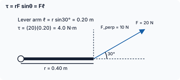
Worked example: an angled push
A 0.40 m wrench receives a 20 N force at 30° to the wrench. The magnitude is τ = (0.40)(20)sin30° = 4.0 N·m. The perpendicular component is F_perp = 20sin30° = 10 N. Multiplying 0.40 m by 10 N gives the same 4.0 N·m.
Alternatively, the lever arm is ℓ = 0.40sin30° = 0.20 m. Then τ = (20)(0.20) = 4.0 N·m. If the force becomes perpendicular to the wrench, torque grows to 8.0 N·m. If it points along the wrench, sin0° = 0 and torque vanishes.
Do not automatically choose the angle between the force and the floor. The equation uses the angle between the force and the position vector. A sketch is usually faster and safer than trying to remember which angle needs sine or cosine.
A force diagram is more than a dot
A free-body diagram centered on a dot is useful for translational motion. For torque, keep an outline of the rigid system or a simple line representing it. Show the application points, relative force sizes, directions, and axis. Gravity acts at the center of mass when analyzing a uniform gravitational field. A support force at the chosen pivot has zero torque about that pivot, even though it can be essential in the translational force balance.
For a horizontal plank pivoted at its left end, a downward force on the right tends to rotate it clockwise. An upward force on the right tends to rotate it counterclockwise. We can choose a positive turning sense and use positive and negative contributions in a one-plane balance. AP Physics 1 expects this one-dimensional bookkeeping and magnitude calculations; three-dimensional torque-vector direction and cross-product calculations are beyond the stated course scope.
Changing the chosen axis changes the torques of individual forces. That does not change the physical forces or the actual motion. In equilibrium, any correctly chosen axis gives a consistent balance. Choosing the axis through an unknown support force often makes the calculation easier because that force has zero lever arm there.
Scaling tells you what to change
At fixed force and angle, doubling r doubles torque. At fixed r, doubling F doubles torque. Changing the angle is not a linear scaling: turning a force from 30° to 90° doubles the perpendicular component, while turning from 45° to 90° multiplies it by √2. A bigger force can still produce a smaller torque if its lever arm is much smaller.
Two opposite forces can have zero net force and still produce nonzero net torque if their lines of action are separated. This is a useful warning: add forces to predict translation and add torques about the stated axis to predict rotation. Neither sum replaces the other.
Instructional example (guided activity):
Table task: Pull a meterstick with a spring scale at several positions and angles while holding the balancing torque fixed. Record F, r, and θ. Compare rFsinθ rather than force alone. Repeating each measurement and reading the angle from a clear top-down view helps reduce uncertainty. State which prediction the table supports.
Worked example — Preserve locations in the force diagram
A freely moving horizontal rigid bar has a reference axis marked at its left end. Its weight is 6.0 N at x = 0.40 m; an upward force of 8.0 N acts at x = 0.60 m; a downward load of 4.0 N acts at x = 0.80 m. At this instant a separate applied force supplies 2.0 N upward at x = 0. An extended force diagram draws the bar and reference axis, with arrows at all four stated locations; arrow lengths have ratio 6:8:4:2 and their directions identify the forces. A dot free-body diagram can show the same forces for translation, but erases the positions needed to analyze torque.
About the marked left-end axis, the torque contributions are −2.4, +4.8, −3.2, and 0 N·m with counterclockwise positive. Their sum is −0.80 N·m, so the bar has an unbalanced clockwise turning effect even though the vertical force sum is 2 + 8 − 6 − 4 = 0 N. The diagram’s application points and axis make this distinction visible; relative force size alone is insufficient.
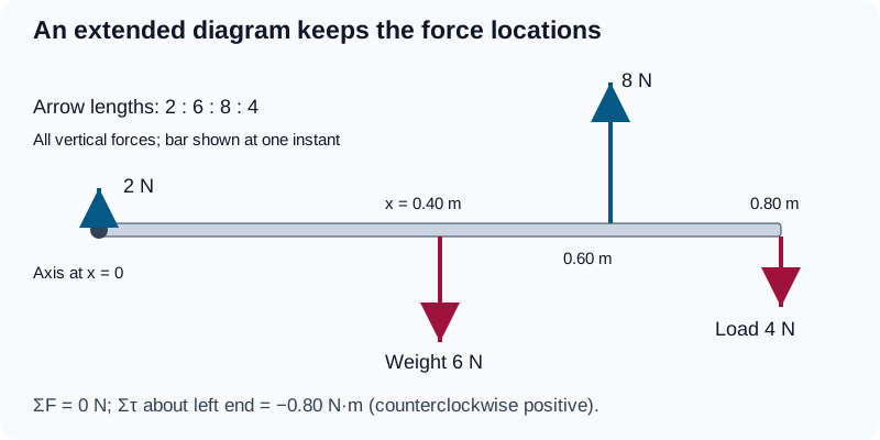
Inspect diagram labels
The diagram keeps its full size here. Focus the view and use the arrow keys, or scroll across it, to inspect every label.
Find the actual lever arm
Pause & try it
Let's see what stuck.
Choose an answer, then check the reasoning. Try the written problems below before opening their solutions.
0 of 3 checked · 0 correct
Assigned practice: competing turning effects
A light horizontal bar pivots at its center. A 6.0 N downward force acts 0.30 m to the left, and a 4.0 N downward force acts 0.20 m to the right. Determine the net torque using counterclockwise as positive.
Open the separate worked solution.
Assigned practice: decide which pull turns harder
A meterstick is held about the same pivot in two trials. Trial A uses a 6.0 N pull applied 0.40 m from the pivot at 90° to the position vector. Trial B uses a 12 N pull applied 0.30 m from the pivot at 30° to that vector. Both pulls tend to turn the stick the same way. A student says B must make the larger torque because its force is larger. Evaluate the claim. Keeping B’s force and angle unchanged, choose a new application distance that would match A’s torque, and identify what distance must actually be measured.
Open the separate worked solution.
The book’s Angular Forces has further force-and-torque examples and quizzes. Its cross-product treatment can stay as clearly marked enrichment; the lever-arm reasoning here is the AP path.
Sources and scope: College Board CED, with edition-specific coverage verified against the supplied file. Supplied College Board CED, printed p. 96, 5.3.A–B and the torque-direction boundary. OpenStax: The Second Condition for Equilibrium verifies the perpendicular lever-arm definition. Our angled-wrench example and diagram are original.
Explain and apply the model
Try these problems before opening the solutions. State your assumptions, show the diagram or calculation, and explain what makes your answer follow.
Construct an extended force diagram
A rigid horizontal 1.0 m bar has a marked reference axis perpendicular to the page through its left end. At this instant force A is 6.0 N downward at x = 0.20 m, force B is 9.0 N upward at x = 0.60 m, and force C is 3.0 N downward at x = 1.0 m. There are no other forces; take counterclockwise positive for the one-plane turning calculation.
(a) Construct an extended-object force diagram of the bar. Mark the stated axis and every force’s application point relative to it, label the source force A/B/C and each magnitude, and draw arrow lengths proportional to magnitude with correct directions. Explain how this diagram resembles a free-body diagram and what a single-dot free-body diagram would erase.
(b) Use your diagram to calculate each torque and net torque about the marked axis. Calculate net vertical force as a separate sum. Explain why equal net force does not determine net torque.
Your written working
Drawing is temporarily unavailable. Work on paper if needed, then record your reasoning here.
Saving written working requires JavaScript. The problem remains available above; keep your work on paper or in your own notes.
Glossary and deeper reading · 8 refreshers
These editorial refreshers supplement the reading. Definitions and examples are added guidance; original source wording and recorded answers remain in their original context.
-
Force
A force describes an interaction that can change an object’s momentum. It is a vector measured in newtons, so both size and direction matter when forces are added. For example, a rope can pull a cart while the floor exerts friction in another direction.
-
Vector
A vector is a quantity with a magnitude and a direction, represented by an arrow or by components along chosen axes. Vectors add by adding corresponding components rather than simply adding their magnitudes. For example, an eastward displacement followed by a northward displacement produces a resultant pointing northeast. The zero vector has zero magnitude and no unique direction.
-
Magnitude
Magnitude is the nonnegative size of a vector quantity. It does not specify direction, and it differs from a signed component. For example, a westward velocity can have a negative x component while its speed, the velocity magnitude, stays positive.
-
Lever arm
A lever arm is the perpendicular distance from a chosen rotation axis to a force’s line of action. It determines the torque magnitude for a given force and need not equal the distance to the point of application. For example, a force aimed directly toward a hinge has zero lever arm and produces no torque about that hinge.
-
Free-body diagram
A free-body diagram shows the external forces acting on one selected object or system. Each arrow names a real interaction, and its direction is the direction of that force. For example, a book resting on a desk has a downward gravitational force and an upward normal force; velocity is not an extra force arrow.
-
Gravity
Gravity is the attractive interaction between masses in the Newtonian model. For spherical bodies or point-mass approximations, its strength decreases with the square of the separation between their centers. For example, Earth’s gravity provides the inward force that keeps a satellite in orbit.
-
Mechanical equilibrium
Mechanical equilibrium means there is no translational or angular acceleration for the system being considered. For a rigid body, both the net external force and the net external torque must vanish. For example, a stationary ladder supported against a wall requires both force balance and torque balance.
-
Net force
Net force is the vector sum of all forces acting on the object or system under consideration. For constant mass in an inertial frame, it equals mass times acceleration. For example, equal upward and downward forces give zero net force even though neither force is zero.