Rotational Equilibrium and Newton’s First Law in Rotational Form
Check force and torque balance separately for rotational equilibrium.
Balanced does not always mean stopped
A wheel can keep spinning at constant angular velocity while the torques balance. That is rotational equilibrium. The condition is Στ = 0 about the stated axis, so α = 0 for the rigid system with constant inertia we are analyzing. Its angular velocity may be zero or nonzero. “Equilibrium” does not automatically mean the object is motionless.
Translational equilibrium is a separate condition: ΣF = 0, giving constant center-of-mass velocity. A rigid system can satisfy one condition without satisfying the other. A force applied through a disk’s center can accelerate its center of mass without producing torque about that center. Conversely, two opposite forces applied along separated lines can give zero net force and a nonzero net torque, making it start rotating.
Static equilibrium means both balances hold and the object is at rest. For a supported plank, this usually requires a vertical-force balance and a torque balance. Draw an extended force diagram showing the plank, its center of mass, the supports, and any loads. A dot diagram alone misses the positions needed for torque.
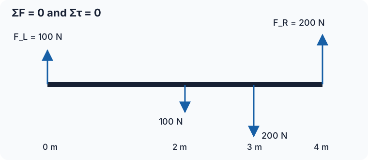
Worked example: load on a walkway
A uniform 4.0 m beam weighs 100 N and rests on supports at each end. A 200 N load sits 3.0 m from the left end. Find the upward support forces F_L and F_R. Assume the beam is stationary, the forces are vertical, and the supports do not exert additional torques.
Vertical force balance gives F_L + F_R = 100 + 200 = 300 N. Choose the left support as the torque axis, so F_L has zero lever arm. Counterclockwise is positive: 4.0F_R − 2.0(100) − 3.0(200) = 0. Thus F_R = 200 N, and the force balance gives F_L = 100 N. The support closer to the load carries more of it.
Check about the right support: the left force contributes −4.0(100), the beam weight +2.0(100), and the load +1.0(200), all in N·m. They sum to zero. A consistent equilibrium does not depend on which axis made the calculation convenient.
A symbolic version shows how the load changes things
For a uniform beam of length L and weight W_b with a point load W at distance x from the left, torque balance about the left gives F_R L = W_b(L/2) + Wx. Therefore F_R = W_b/2 + Wx/L. The remaining support is F_L = W_b/2 + W(1 − x/L).
Moving the load right increases F_R linearly and decreases F_L linearly. The sum stays W_b + W. Sketching support force against x gives two straight lines; at the midpoint they are equal. If an equation predicts a negative force from a support that can only push upward, the assumed contact configuration fails. The beam may lift off or tip rather than having that support pull downward.
Torque balance is not force balance in disguise
Consider a horizontal bar with a downward force on its left and an equal downward force on its right, equally far from its center. Their torques about the center cancel, but the net force is downward. It can accelerate downward without changing its angular velocity. Now put equal upward and downward forces on opposite sides: the net force is zero, but the turning effects can add. It rotates without accelerating its center of mass.
If the net torque on a rigid system is nonzero, its angular velocity must change. It might speed up, slow down, or reverse, depending on the current rotation and turning sense. A steady nonzero ω has a horizontal ω–t graph, a straight θ–t graph, and balanced net torque. No continuing unbalanced torque is needed to maintain its ideal steady rotation.
Instructional example (guided activity):
Balance task: Support a meterstick at an off-center pivot and hang two known masses at measured positions. Use torque balance to infer the meterstick’s mass, then compare with a scale. State a specific uncertainty: measure positions to the centers of hanging attachments, not just their edges. Repeat with different placements and explain why consistent results strengthen the model.
Worked example — Test the two equilibria independently
A freely moving bar of mass 2.0 kg has I_cm = 0.10 kg·m². Ignore other forces for these two ideal force arrangements and choose upward and counterclockwise positive. In case A, two 4.0 N downward forces act 0.20 m to either side of the center. A dot free-body diagram shows net force −8.0 N, while an extended force diagram shows torques +0.80 and −0.80 N·m about the center. Thus a_cm = −4.0 m/s² and α = 0: the bar is in rotational equilibrium but not translational equilibrium. If it initially spins at +2.0 rad/s, that angular velocity stays constant while its center accelerates downward.
In case B, a 4.0 N downward force acts on the left and a 4.0 N upward force on the right, again 0.20 m from the center. The free-body force sum is zero, but the extended diagram gives two +0.80 N·m contributions. Thus a_cm = 0 and α = +1.6/0.10 = +16 rad/s². The unbalanced net torque requires angular velocity to change: it grows by +4.0 rad/s over 0.25 s if the arrangement maintains those lever arms and torques. Translational equilibrium alone does not fix the spin.
Balance both ledgers
Pause & try it
Let's see what stuck.
Choose an answer, then check the reasoning. Try the written problems below before opening their solutions.
0 of 3 checked · 0 correct
Assigned practice: a seesaw with its own weight
A uniform 2.0 m board weighs 60 N and is pivoted 0.80 m from its left end. A 100 N load hangs from the left end. What downward load at the right end balances it?
Open the separate worked solution.
Assigned practice: use the off-center balance
A uniform meterstick is horizontal and balanced on a pivot at its 0.40 m mark. A 0.20 kg mass hangs at 0.10 m and a 0.10 kg mass hangs at 0.90 m. The meterstick’s mass is unknown; neglect attachment masses. Infer it without using a scale. Then predict which way the stick would initially turn if the pivot moved to 0.50 m while both hanging masses stayed in place. Explain why the meterstick’s weight matters in one configuration but has zero torque in the other.
Open the separate worked solution.
The original Angular Forces keeps its force diagrams, examples, and quizzes. Use both ΣF = 0 and Στ = 0 when it describes a stationary extended object.
Sources and scope: College Board CED, with edition-specific coverage verified against the supplied file. Supplied College Board CED, printed p. 99, 5.5.A and the single-plane boundary. OpenStax: The Second Condition for Equilibrium verifies torque balance and lever-arm reasoning. Our support and seesaw tasks are original.
Explain and apply the model
Try these problems before opening the solutions. State your assumptions, show the diagram or calculation, and explain what makes your answer follow.
Separate translation and rotation
A freely moving bar has mass 2.0 kg and provided I_cm = 0.20 kg·m². Ignore all other forces in this ideal comparison. In arrangement A, two 5.0 N forces both point down, one 0.30 m left of the center and one 0.30 m right. In arrangement B, the left 5.0 N force points down and the right 5.0 N force points up. Upward and counterclockwise are positive.
(a) For arrangement A, draw both a dot free-body diagram and an extended force diagram about the center. Use the first to find net force/a_cm and the second to find net torque/α. Decide independently whether the bar has translational and rotational equilibrium. If initial ω is +1.0 rad/s, predict whether it changes.
(b) Repeat the separate force and torque sums for arrangement B. State the two equilibrium judgments and explain why the unbalanced torque requires angular velocity to change. Find the initial rate of change of ω; if an apparatus maintains this net torque for 0.10 s, find Δω.
Your written working
Drawing is temporarily unavailable. Work on paper if needed, then record your reasoning here.
Saving written working requires JavaScript. The problem remains available above; keep your work on paper or in your own notes.
Glossary and deeper reading · 8 refreshers
These editorial refreshers supplement the reading. Definitions and examples are added guidance; original source wording and recorded answers remain in their original context.
-
Angular velocity
Angular velocity describes the rate and direction of rotation about an axis. For a fixed axis, a signed angular velocity is measured in radians per second, while its magnitude is angular speed. For example, points on one rigid turntable share the same angular speed even though outer points have greater linear speeds.
-
Torque
Torque describes a force’s turning effect about a chosen axis or point. Its magnitude is force times the perpendicular lever arm, and its direction or sign describes the rotation tendency. For example, pushing near the handle of a door produces more torque than the same perpendicular push near the hinge.
-
Velocity
Velocity describes how position changes with time and includes direction. Instantaneous velocity describes one moment, while average velocity is displacement divided by elapsed time. For example, a car turning a corner can change velocity while maintaining the same speed.
-
Force
A force describes an interaction that can change an object’s momentum. It is a vector measured in newtons, so both size and direction matter when forces are added. For example, a rope can pull a cart while the floor exerts friction in another direction.
-
Center of mass
The center of mass is the position obtained by weighting each part’s position by its mass. Its motion represents the translational motion of the whole system under the net external force. For example, adding a heavy object to one end of a light bar shifts the center of mass toward that end.
-
Net force
Net force is the vector sum of all forces acting on the object or system under consideration. For constant mass in an inertial frame, it equals mass times acceleration. For example, equal upward and downward forces give zero net force even though neither force is zero.
-
Weight
Weight is the gravitational force exerted on an object by a specified attracting body. Near Earth’s surface its magnitude is approximately mass times the local gravitational field strength, and it is measured in newtons. For example, an astronaut has less weight on the Moon while retaining the same mass.
-
Free-body diagram
A free-body diagram shows the external forces acting on one selected object or system. Each arrow names a real interaction, and its direction is the direction of that force. For example, a book resting on a desk has a downward gravitational force and an upward normal force; velocity is not an extra force arrow.